My thought process is that it seems like an overkill in terms of complexity. A majority of the component count is there just to run and interface with the microcontroller; resistors, capacitors, regulators, LEDS, micro-USB, powersupply, cyrstal oscillator, etc.
What if we designed our own motherboard that only mounts components that are relevent to the throttle (barometric sensor, throttle pontentiometer, pin headers for display, etc) and off loaded the rest to a daughterboard that can be bought off the shelf (ie Arduino Micro).
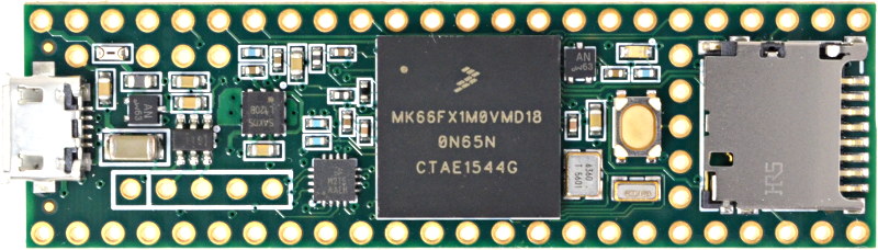
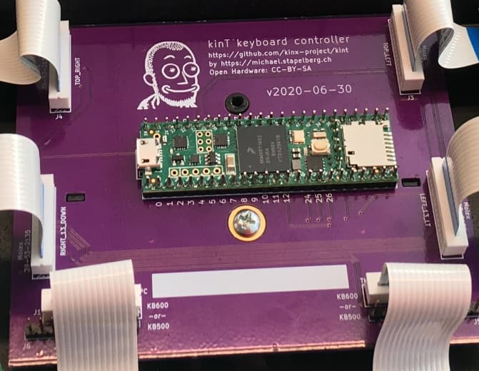
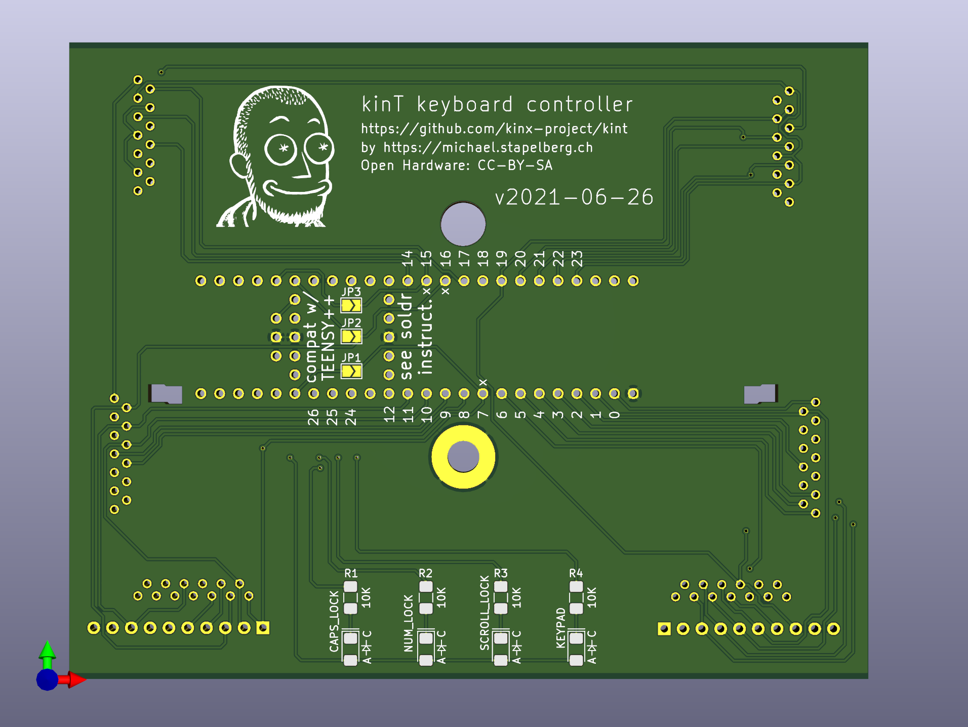
A prime example of this is the kinT board for the Kinesis Advantage keyboard. The daughterboard (teensy) is bought off the shelf and soldered onto a motherboard that is custom made (by Michael Stapelberg). Kinx-Project
With the current design we have everything on one single PCB. A throttle that uses a splitboard design has the following advantages are:
Easier Servicing Of Hardware - With a split board design you can cheaply replace the daugter or mother board. Easily replace broken parts (ie. Linear Motion Position Sensor) on the motherboard due to its simplicity.
Cheaper Manufacturing - We just buy off the shelf daughterboard (ie arduino micro) and plug it into the motherboard. The motherboard is cheap since it is extremely simple and doesn’t require extensive component placement or SMD soldering. The off the shelf arduino board is extremely cheap because of economy of scales.
Improves Reliability - The off the shelf arduino board is well… off the shelf. There are millions of these arduino boards that have been tested in a variety of environments. We will just need to worry about the reliability of the motherboard (not a problem due to low component count).
Faster Prototyping - You can cheaply and easily modify the motherboard. For example download a BLE chip placement plan and easily incorporate into the motherboard. Generate gerber and couple days later you get your PCB. Solder in the daughter board and the few components that go onto the motherboard PCB and you are ready to flash the daugterboard.
Easier For Hobbyist - Hobbyist won’t need to be concerned with Arduino component layout. They will just need to add/modifiy footprints for the component they are adding and route it to a free pin on the daughterboard (ie arduino micro) that will get attached.
The downside is that:
We might need to put a bit more effort into layout to accomodate the off the shelf daughterboard.
Hopefully I made sense and didn’t confuse you guys. If you have question or clarification don’t hesitate to ask.
I think you nailed many of the advantages of using a separate daughter board design.
After all, many of our prototypes have started with an off the shelf Arduino variant and all of the components connected via a breadboard and wires.
I bought a few variations of the Seeeduino XIAO board recently to prototype with. They seem to be some of the most promising options as the formfactor is very compact and pretty cost effective. I’ll definitely be keeping an eye on those and similar boards.
From my perspective, there are a few other downsides of that approach.
Firstly, as you may have noticed, many of the Arduino boards, including the Seeedstudio ones have been either out of stock or only available in limited quantities for the last ~2yrs. This presents a problem when we already have a motherboard built out for a specific off the shelf Arduino thats unobtainable. We’d either have to switch to another board option and update the layout + pins etc. or just wait and be at the mercy of someone like Adafruit.
In the latest batch we’ve had to work around many chip shortage and supply chain issues by swapping out components and redesigning the PCB but it was worth the tradeoff as we were able to secure large quantities of chips (100s) from global suppliers like Digikey.
Speaking of companies like Adafruit, many of their Arduino designs are available for reference so there isnt a ton of reinventing the wheel design wise which helps with reliability.
Cost of manufacturing seems negligible once you hit 50+ PCBs. Yes there are economies of scale for the Arduino board manufacturers but they also have to make a profit. We take advantage of Chinese PCB manufacturers that do assembly in-house so thankfully its fairly affordable. Once you send them the completed design they can crank out boards in just about any quantity.
All that being said, we’d love if we didnt have to do any custom designs. Hardware is… hard
But since I still havent found any decent electric paramotor throttle systems here we are haha.
It sounds like you have some electronics experience so feel free to pass along any further feedback. Also, Im always looking for more capable yet simpler and affordable Arduino boards to build off of so let me know if you find other options.
Being attracted by the title… That’s just what I’m looking for at the moment…the simplest throttle for a MAD esc without bec. Don’t know about programing so from little research that I did I saw people taking the board from a servo tester, replace it’s potentiometer with an electronic bike throttle or something like that to make a throttle for e-skateboard. I know it sounds ancient compared with what’s written above but is that doable for a paramotor?
Are there somewhere such simple throttle already made that would work out of the box with such an esc?
most esc work very easily with a pwm module. a servo tester board and a potentiometer as a linear potentiometer can be used very well as a basis. if the esc does not provide 5 or 6 volts, you have to supply the circuit board with 5 or 6 volts like a receiver on an rc flight model. there are also wireless systems from other areas that are conceivable to fly with. e.g. the maytech throttle which is otherwise used for e foils. here the receiver also needs a supply of 5-6 volts from the esc or from a small battery. esc from mgm, for example, can also be controlled directly with just a potentiometer or other signal generators. a very quick solution is to simply use a normal petrol ppg throttle grip and simply attach the cable to a servo tester with a small lever. i have been flying successfully on a number of projects for over 10 years. mostly with the cameleon 2 throttle grip.
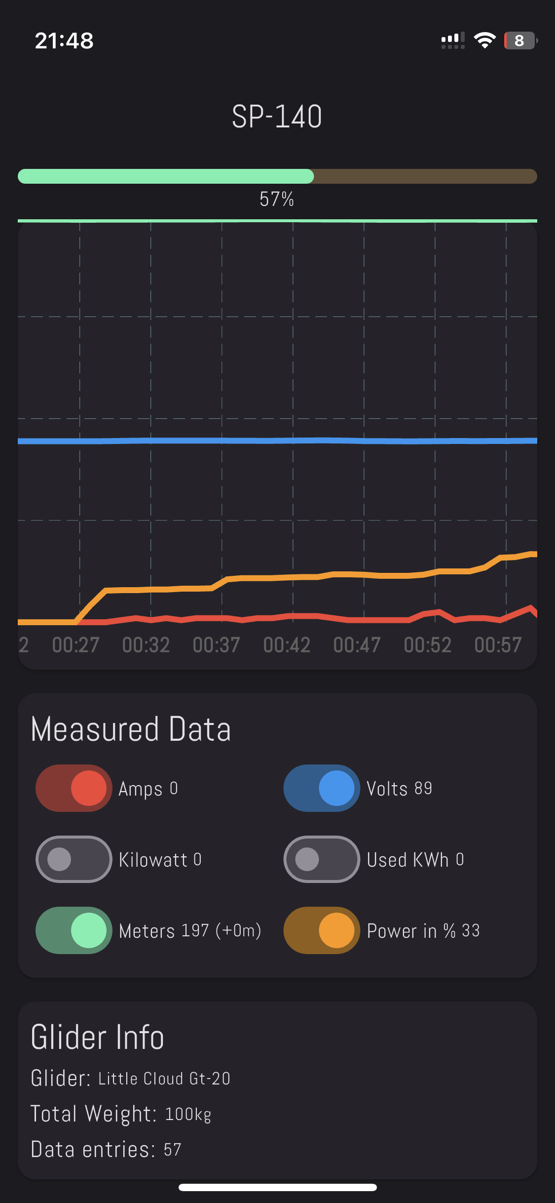
Following the idea that a simple servo tester can control an esc, and watching some Polini’s throttle handle photos, I’ve managed to build a throttle controller using the material I know how to process - plywood. Inside there is a simple servo tester on which potentiometer shaft I’ve mounted a toothed pinion. The toothed wheels are from used printer cartridges. I’ve build it more or less around of an wireless coulometer display that shows voltage, amperage, wattage, remaining capacity, used capacity, probe temperature, timer, you name it.
The red switch on top arms/disarms the esc. It has 143 grams and an adjustable elastic band over the hand with velcro.
Then I’ve applied four layers of black spray paint and two of transparent varnish.
Tested on three different rc 30-70A escs they all work fine. Because it’s 300A it’s not sensitive to current below 1A so it starts showing it after it passes 1A.
Some photos below and a video with it workig.
I love it!
Thanks to everyone for their help!
reminds me a lot of when i built my first hand throttle grips with gears and toothed bars. even if i don’t fly dami anymore these individual pieces are still in the workshop and when i have visitors i like to show “how it all began” you do it right with learning by doing. these experiences are the best basis for development. wood is often the easiest and best for individual pieces and prototyping. I wish you nice flights.
Not yet. Just about to do some ground testing these days after I build some frame that holds the paramotor in place. Didn’t rush to much as all the grass fields had knee high grass, they just start to mow here and there.
I recently bricked my throttle controller (here). Looking at the shipping and import cost and time to Estonia, I thought of making a minimalist throttle for the time being.
I used the Xiao ESP32-c3. I tried to keep it simple hardware-wise, so I log all the data to my phone via BLE. The altitude is also measured by the phone not the controller.
I only tested it without prop but it works well so far.
It also lacks some features such as cruise mode and Sport/Normal mode.
Nice, I really like it. Especially the physical switch. I doubt my risers would activate that.
Whats the durability on the spiral spring that you integrated with the gear?
To break the spiral I had to force it 3 times beyond its normal rotation range it has when inside the controller. The throttle has also survived some harder landings.