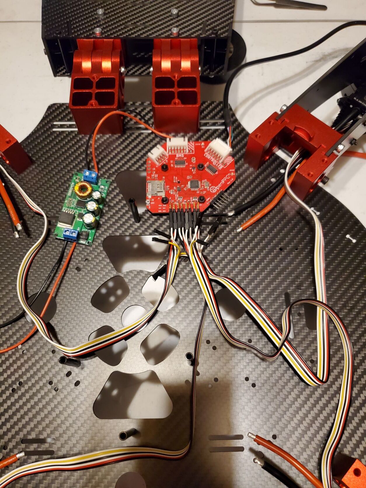
Hi all. I got an X4 kit last month and I’ve mad a fair bit of progress in assembly. I didn’t appreciate when I bought it some of the challenges along the way with older documents and videos and revisions to the kit since then. That said, I have perused the message boards looking for help or photos on how to connect the last bits. I think I know what I need to do to solder the heavy power wires to connect the batteries. At least there are some photos of that to check against. It’s the control wires that I’m not sure of because it’s changed since the assembly video. Can anyone give me a pointer for what connects to what in this picture?
Note the bottom red power wire. If one switch fails, it allows both pairs to stay connected. The only thing you have to be careful about is not leaving the batteries connected…even when the switches are off; otherwise, one pair will constantly try to charge the other pair. Plug the batteries in JUST before your flight and disconnect the battery plugs immediately after your flight…after both switches are turned off.
Sorry that I’m not much help with the control wires. Bill
Thank you Bill. That’s a great picture. I’m going to pick up some more wire today to finish the power wires. My kit had two short segments that I don’t think will be quite enough. The control wires are a bit of a mystery to me. Nothing I’ve found so far tells me what if anything to hook up the other wires to.
thanks for pointing that out. I think that’s the one that helped me get some of the connections. there’s another post with an annotated photo with lines drawn on it showing the same thing. I am just not sure if the other connections on the controller need to be hooked up to anything. I guess I can find out when I get my power lines hooked up. I ordered a second switch and some more 8ga wire so I can do that work in a couple of days.
There are some spare sockets on the hub board that don’t need to be connected to anything. It looks like you have connected correctly at 1st glance. Be careful to connect the esc wires correctly. There is a good photo from gliderpilot which explains it well. Careful to start from the correct end of the row of pins.
that is gliderpilots diagram… he says…For telemetry (marked in green) plug in the the white, red, and black. The white goes on top and the black goes on the bottom for both. The last two wires on each ribbon are not used (yellow and white).