While I wait for a resolution from @Pdwhite for better CG. I’ve started on the recommended fixes and ‘upgrades’.
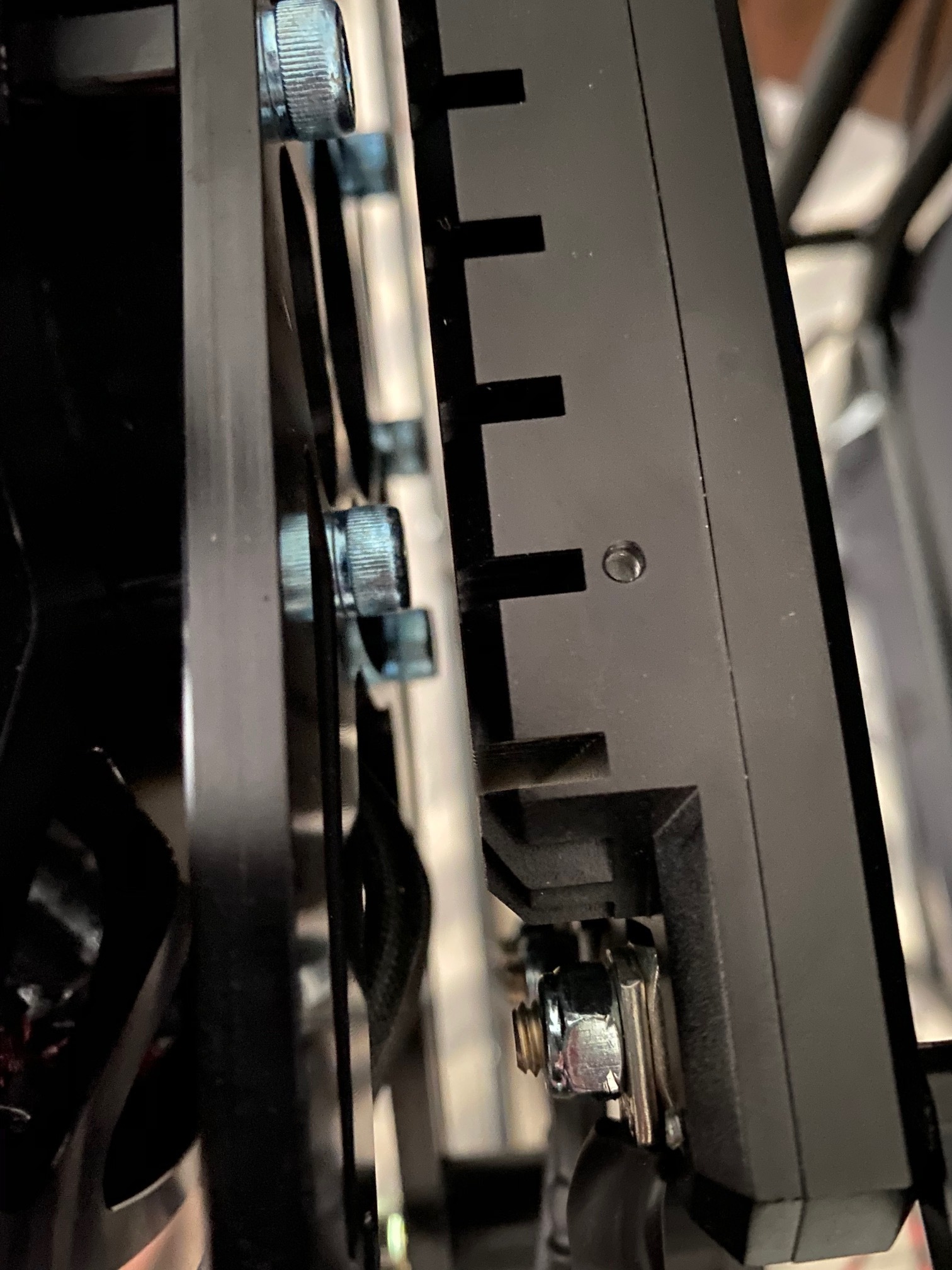
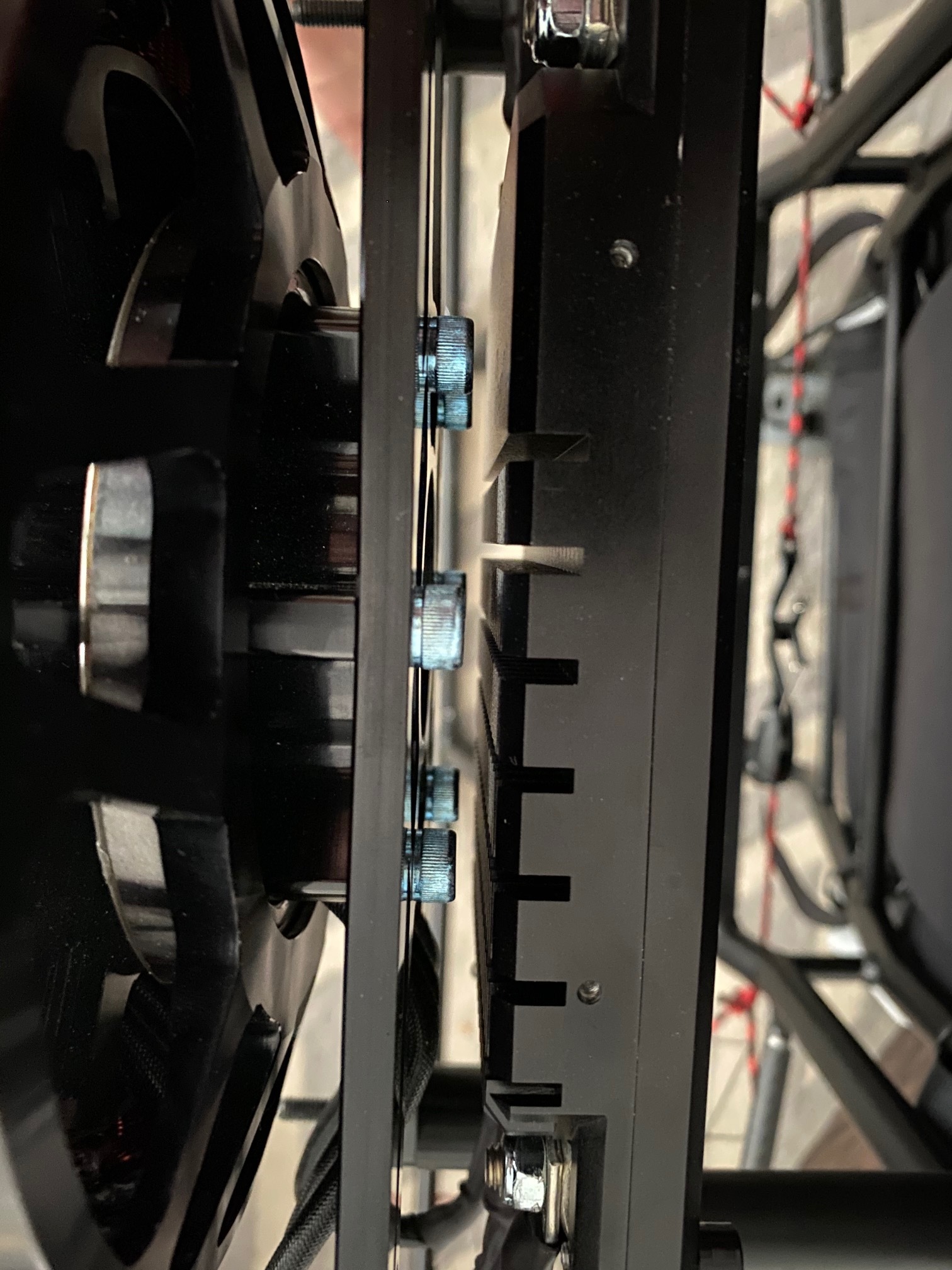
Original spacer is ~ 22mm W x 53mm H with an internal diameter hole of ~8mm
New spacer is 22mm W x 38mm H with a hole of 6mm (gives the bolt a tighter fit)
I’m using PETG 100% infill ‘carbon fiber’ filament
I estimate about 5mm of spacing between the bolts of the motor and the ESC after reducing it by 15mm
I’m going to try a simple cover that will attach to one of the spacers.
Thanks, it’s PETG I don’t think there’s actually any in there, but I’ll double check.
EDIT: just ran ~24V @5 amps through a test print. Doesn’t trigger a short circuit on the power supply, so I’m good.
Thanks for the warning!
I think you need to be a bit cautious here - the battery has up to ~96v on it and if there is any conductivity in your material, this might not let much currnent through at 24v, but at 96v might be enough to heat/melt the material with a catastrophic breakdown… if it is pure PETG there should be no problems as it is a good insulator, but if there is a carbon fibre load in it you might be in trouble…
Sorry if that was pedantic. I do think clarity counts for a lot in these types of discussions where one does not have the benefit of ‘non verbal’ part of the communication (although… technically it’s all non-verbal…)
Error on the side of caution is prudent. This is aviation after all. Not being sure might make for a very bad day indeed.