@Pdwhite do you have a picture of the connections to the SP140 ESC? - I had to unplug mine to repair the cable (it had pulled out of the throttle body) - I took a photo of the connections before disassembly, but now plugging it back in, it doesn’t seem to coincide with the diagram printed on the ESC… Hunted high and low as I seem to remember seeing you mention it in a video, but can’t manage to find it. - Just wanted to check before I fry something!

Perfect, thanks!
my ESC looks a tiny bit different - the 10.5v @60mA is marked nc, and the connector with the wire missing goes on the other set of pins which is what confused me!
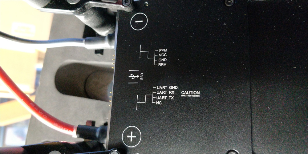
Does anyone know if the controller is powered by 10.5V or if it is transformed down to 5V? I have the same version as @Billwhite which just says NC but since the white wire that goes from the ESCs` NC into the controllers VIN I thought this is coming from the ESCs BEC.
On that note I also saw the note “CAUTION UART non-isolated” and was wondering how the controller handles this.
I am asking as I wanted to experiment with different controllers
This ESC is specifically built for OpenPPG (notably the additional power output). The markings may slightly differ but the functionality should be the same for the all current SP140 ESC versions.
Traditionally with an ESC like this, there is a high side, and a low side.
The high side contains the fets, high current, and voltage (100+v) operations dealing with the brushless motor.
The low side contains the microcontroller, which handles communications, like UART and PWM and operates at less than 12v (5v, 3.3v etc.)
Its common practice for the low side is isolated from the high side to reduce the risk from blown fets or interference impacting the sensitive low-voltage circuitry. Because of this, each side needs to be powered separately. The high side is connected to the battery, so that’s already covered. Since the SP140 only has one power source, the low side (5v) gets its proper voltage by going through the controller’s protected linear voltage regulator. That steps it down from ~10.5v (high side custom output) to 5v (low side input). Don’t quote me on the numbers, but that’s right from what I remember.
If you’re going to work on your own controller, test to make sure you’re connecting the right voltages to the right pins. The ESCs arent cheap if you have to replace it because you fried it!
2 Likes
Thanks for the clarification regarding the input voltage. I just have one remaining question regarding the UART connection. The guide on their website states the following:
The UART output is not isolated from the signal input connections. The output must be connected to a different device to the signal generator. Failure to do so will result in permanent damage to the unit.The UART output is not isolated from the signal input connections. The output must be connected to a different device to the signal generator. Failure to do so will result in permanent damage to the unit.
UART Telemetry Output - Advanced Power Drives
I just wanted to make sure I don`t accidentally connect the UART pins to the signal generator (which I assume is another part on the esc?). Is there any possibility I could run into this issue when I just connect to the controller?
If you’re talking about just connecting to the PWM side it sounds like you should be fine. Again, not 100% sure and Id trust the APD docs more than my memory.
I think connecting it directly should work as long as the “NC” pin is used to power the controller and not a separate power source as you only have one common ground (UART GND).
I asked the APD support and they recommended using a separate power source and isolating the UART using an optocoupler.
Because the original SP-140 controller is powered through the ESC, I would assume it doesnt isolate the signal but I dont have the SP-140 controller pcb layout so I dont really know how it is handled there. Do you know anything in that regard, @zjwhitehead?
Recommendation by APD:

Is the SP-140 controller pcb layout available somewhere or does someone know how the UART is connected?
Have you looked at the code yet? The UART is just set up to one of the boards serial connections. See eppg-controller/rp2040-config.h at 7976f151702fe4521b192346fd340134ee566ed3 · openppg/eppg-controller · GitHub
It’s a standard hookup: TX->RX, RX->TX
Thanks! I got it working. I was just not sure if the SP-140 controllers microcontroller is directly connected to the UART of the ESC
1 Like