How does the low power cut off mechanism in the SP140 work?
Is there any? I guess there is
Is it controlled by a voltage threshold stored in the ESC or by the BMS (included in the battery)?
What is the cut of value for the 24S battery used in the SP140?
My assumption is that the ESC does not have a threshold value, but does rely on the BMS to cut the power once the voltage drops too low.
If that is the case the follow up question is: Does the BMS used in the SP140 batteries monitor each individual cell voltage for reaching the low threshold cut off value, or does it only monitor the total cell voltage?
If I remember right there is an absolute low cutoff at 2.6V per cell group in the BMS just to protect the cells, but this shouldn’t be used as a cutoff to let you know your battery is dead. If you reach that point then you may either have a parasitic cell (like I unfortunately have) or you’re running your pack way too low for repeated use. It may also unexpectedly cut from the voltage sag during full throttle near the end of your flight so watch out for that. And yes, the BMS monitors each cell group. Hope this answers your question.
I believe there is an option in the ESC configurator to add a low voltage cutoff or even a soft cut, but that isn’t currently utilized for safety reasons. It’s better to pay attention to the voltage than it is to have an unexpected cutoff.
Just after writing the question I hit the cut off during a rather short flight. Briefly before that the voltage under load was displayed around 72 Volt. Going off throttle it got up to 82 Volt again.
6 Volt voltage sag feels like quite a bit to me, but maybe this is just because I have been using larger batteries before.
What is the best way to identify and deal with a parasitic cell (group)?
When and how does the used “Smart BMS Daly” balance cells?
while charing or after charging?
only in certain voltage range? (e.g. only if the average is above 4.1 Volt)
I dislike the Black Box nature of the BMS.
Batteries are expensive these days and more insides would help us all to fly more and at the same time protect the investment and the environment.
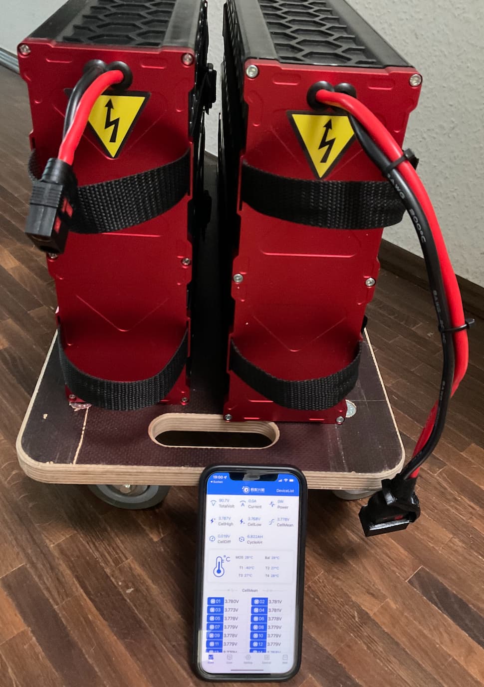
Each column is just a different day and arbitrary charge level that I measured. From these measurements my guess is either the BMS tolerances aren’t the best, or it’s a parasitic cell that’s pulling down the rest of the voltage in cell group 18. I think it points to a parasitic cell since the low group is further off at the low end of the charge. The BMS balances the cells only during charging according to Paul. I’m not sure if it only tries to balance during a certain voltage range.
Also if you are going from a 4kwh battery to a 2.2kwh battery there will be more voltage sag expectably if using high power. And for reference the 2kwh pack is rated for 5.5 kw continuous discharge were as the 4kwh pack is 10kw.
The cell cutoff is 2.5v so it really shouldn’t be used if it can be helped. I am testing some “smart BMS” (Smart=Bluetooth) right now. So if it works well it will be changed in the new battery’s and should be able to be swapped with older batteries
Thanks for the confirmation @glydrfreak !
I was expecting that and did use another charger (Chargery Power C10325, 4-24S, selectable Battery type, selectable target voltage, selectable charge current <1 to 25A) to slowly charge the battery at 1A and not at 10A as the SP140 default charger does.
I also did take a measurement and one group was clearly off, but not as much as in your case.
This basically boils down to the question if the cell group can be restored to a certain extend by several slow charging + balancing cycles without physically swapping a (couple of) cell(s).
Thanks for the confirmation @Pdwhite !
Is there a way to restart the ESC without pulling off the battery and plugging it back in after the cut off?
This is kinda tricky in flight
It would be good it a better BMS also supports balancing while the battery is not charging (as the ANT BMS does that I have been using). A typical use case is that you have your battery charged to storage level voltage. The BMS should slowly balance all cells. Then you charge it to max and leave to the take off. In my case that takes >1h until I am able to take off and the BMS would have some time to balance the cells again.
It is doable, but a lot of work and definitely not without risk.
“Electric Fox” upgraded my Battery pack by replacing the Daly BMS with an BT-enabled ANT BMS, which is also rated for 200A permanent load, not 100A (which I easily exceed on the initial climb with the light trike). In addition I got a button mounted to turn it back on.
I can turn off the discharge MOS => the plug is not dangerous any more during normal handling. Reminder: 60+ Volt shocks can be lethal!
I have a chance to understand what is going on the inside and e.g. get an early warning when a cell group drops far more than the other cells => less risk of deep cycle damage
Now I can also manually trigger balancing at lower voltages and do not need to fully charge first.
Being able to turn on/off the BMS does save energy when the battery is in storage
Weight change is only a few Gramm, impossible to notice
Unfortunately that did not fully fit in the original housing and thus there is now a little 5mm gap on top. At some point I need to 3D print a kind of ring to close it.
Very nice. I agree 100% and read a number of times they would be included in this latest batch, which is part of why I was waiting to purchase. Waiting to see if this is the case or not?
I’m not sure if this is the right thread to post to, or if I need to start another one. But I received the new battery with the bluetooth Daly BMS that is the new V2 Battery. But when I plug it into my motor it immediately shuts down, and I see in the bluetooth app that the Discharge MOS is disabled. I have to go in the app and enable the discharge MOS.
I also have noticed that when charging, the battery only charges to 99.8V rather than 100.2-100.8 like my 4kw battery does. It appears this is because the BMS is cutting off charge, but when I connect with the app and watch it during charge, no cell is exceeding the 4.2V.
Is something configured wrong, why would it be doing this?
Yes the new BMS that ships has BT and you can change the cutoff voltages to whatever you like. I wouldn’t go above 4.2v but you can if you think its not charging high enough for your liking.
The MOS is turning off because its thinking there is an overcurrent/short from the esc first getting up to voltage. So plugging in the connector half way then plugging in all the way on the precharge is done will eliminate that start up current. Also can set a higher current discharge cutoff and that should also fix that.
Just a comment from the EV world… The pack is never disconnected while driving, except in the case of a crash. The BMS will alert the inverter (speed controller) about low state of charge or low cell voltage, and it will reduce power. If you keep going you will get all kinds of warnings, turtle lights, sounds and further power reduction. Eventually it will stop before you hit the low cell limit.
It worries me a bit to have a semiconductor switch in line - in the case of low cell voltage, sorry I’d rather damage the pack than my legs And there’s extra failure modes - the FET itself could blow or the logic controlling it could cause a false shut-off.
The “pack protects itself” model is what the e-bike world uses. That’s fair enough, you’re never in danger from losing e-assist. The R/C world uses “BMS warns you” strategy - like those screamer BMS circuits. That’s because people don’t want to lose their model plane! And cars, well, you don’t want to stop dead on the highway or in a junction, but the pack is very expensive so you want to protect it also.
IMO when it’s supporting a human, the safety risk of losing power suddenly is even higher than for cars, and we should aim for the safest strategies from that world (accurate warnings and power reduction).
So what is the status of newly shipped units. Can you adjust LVC on the controller?
The best would be 2-steps
First one could be when you reach around 3V/cell or 72V on the whole pack on controller side. This will cut the throttle under load but will not shut down the system(battery), so you can still spin it up for a landing.
Second stage is that below 3V and will be last cutoff made by BMS itself that will shut down the battery itself.
Options are None, Hard Shutdown, Gradual Shutdown, 75% Power Limit, 50% Power Limit and 25% Power Limit.
So perhaps one can set it to either gradual shut down or power limit of 75-50% so you know its time to land when you feel that the limiter is kicking in. Now of course, you could look at the display, but would be good to have that extra “safety alarm” if you get carried away during flight.
One of the keys to a long battery life cycle is to ensure that the propulsion device does not use the full capacity of the battery. If you want to enjoy the pack for a long period, do not charge to absolute maximum e.g. 4.2V per cell (100.8V). Instead you can use 4.15-4,1 (99.6V-98.4)
Same goes with Discharge. I do not recommend going below 2,8V/cell or 67,2V in a full pack.
I’ve been using the pack from 100.2V to 80V. I have found that the 70-80V range runs out just about as fast as the 98-100V range. So you get much more out of the pack without stressing it by charging up to full and ending early, rather than charging up to 98V and running down to 70v.
With that said, Allex you are totally right about longevity of the pack.
But lets say you were to use it’s full capacity 4.2 to 2.5V every single flight, under hard load. Strenuous usage of the pack, from the Molicel Datasheet, you can expect 85% pack capacity after 500 cycles, or 500 hours of flight.
That seems like it would take years ( assuming 100 hrs flight per year ) for us fair weather fliers to actually see appreciable capacity loss. The capacity of the pack would degrade over 5 years just as much if not more due to age, than from how you are cycling the pack.
In conclusion, charge it, send it, cool it, store it, forget about it.


 And there’s extra failure modes - the FET itself could blow or the logic controlling it could cause a false shut-off.