I suddenly lost power about 25 minutes into my flight the other day. This happened while using only 5.6kW at cruise control for about 4 minutes. In the air I decided to try and power cycle the BMS, but when I reached back I discovered one of the wires had come unsoldered from my connector. Furthermore the connector was melted together so there was no getting it apart.
My flight was conservative, only using full power for less than 15 seconds for take off, and one more short burst of power to climb out of a field for 15 seconds. My ESC logs never showed anything above 70°C and nothing else in the logs looked out of the ordinary.
My theory of what happened was the wire slowly unsoldered itself little by little over the past 10 flights. I haven’t abused the throttle enough for something like this to happen, so there must’ve been a bad solder joint. I don’t hold this against Paul, because I’ve learned first hand that these qs8 connectors are not easy to solder. I did discover a large sludge of flux on the wire that could’ve been inhibiting the connection. I’m sure as the solder bridge gets smaller and smaller, it takes less and less power to heat up.
So I went on to replace the qs8 connector. I removed the two power wires for the ESC to make soldering easier. But when I went to put the wires back onto the ESC studs, one of the studs effortlessly torqued off. So warning, these aluminum studs can only be torqued once! Luckily APD can fix this. The stud is soldered and press fit to the PCB. They have the proper tools to replace this stud for me.
Bad solder connections are the bane of anything electrical. Did one myself on one of my X4 battery connectors despite being extremely careful not to and having a lot of experience monkeying old cars. Luckily mine just pulled apart when I was unplugging it rather than melting under load. Mechanical stress, plugging and unplugging, can also slowly corrupt an already bad solder joint.
I am not surprised with the QS8 - they are hard to solder. I was pre-tinting wire and connector and then joining – You have to have an opposite part of the connector on in order to apply enough heat and not let the metal move in the plastic.
As for the stud –
Aluminum is an “ok” conductor – 61% vs 100% copper. And copper is apprx 40% stronger in tensile,from what have Googled
Cheers
I certainly understand the solder joints…it takes lots of heat in a really short amount of time to do it properly. I bought a very large iron and controller just to build my X4. What I don’t understand are the aluminum posts on a VERY expensive ESC. The price of that ESC makes up a significant part of the cost of the 140. I hope the warranty and service department of that manufacturer are first rate and the “turn around” is short. I’m sure Braedin will keep us updated. Bill
When it initially broke, it didn’t look like a brass core, but rather looked aluminum. Then overnight the core seemingly changed color to brown. That left me pretty confused about the material and finish. now we know.
Haven’t seen one of those before but it does not look like there’s a sufficient contact area where the cable joins the connector. What did you replace it with?
Blockquote
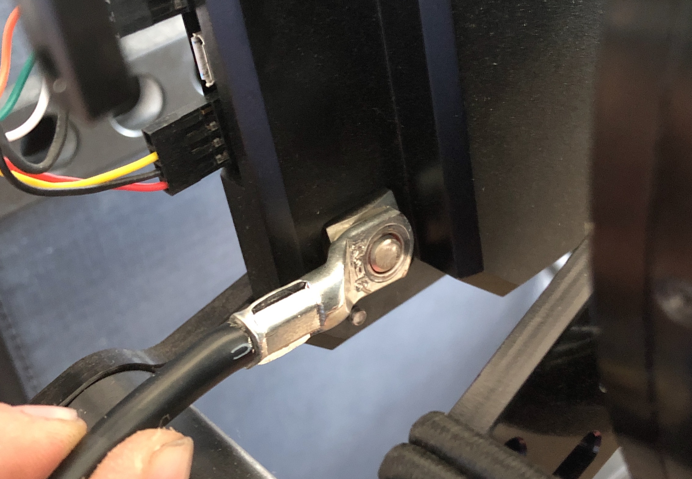
torque spec of 3.9 Nm
So…put a wrench on it and breath in it’s general direction.
I just replaced it with another qs8. There’s actually plenty of surface to make contact in the connector. Just have to make sure to have good craftsmanship. Still no problems and I’ve put at least 5 flights on it since this happened. I repeatedly reach back and feel the wire temperature during flight now cuz I’m paranoid it might happen again.
What’s the gauge of wire used? I need to go back and check a post I made because I think I overstated the wire required, looking at the published maximum, instead of a likely sustained. It seems like 1 gauge or aught would be advisable given a potential 15kW climb-out that would need somewhere in the neighborhood of 150A depending on voltage state.
I also notice in your picture that you could possibly flip the controller and motor and take out maybe 3" of cable.
It’s 8 awg wire. I was going to swap it for 6 awg, but I determined it would’ve been more of a job than what it’s worth since I’d have to replace the wires buried in the battery pack. My wires get pretty warm, but never too hot during a 1 minute full throttle climb.
I fly at high take off elevation so my numbers are very subjective, but full throttle gets me about 600 fpm of climb with my EN-A wing. I bet others at sea level could get nearly 1000 fpm.
@Pdwhite said he’s done a full throttle ground test for 5 minutes I believe. I typically only do full throttle for short fun bursts. If I’m climbing just to gain altitude, I usually just set the cruise around 10kW. It’s a more efficient climb and plenty fast climb rate for me.
600fpm! Wow. Flying 6s bonkas instead of seven that my batch 4 was designed for really cuts into that. At full power with four bonkas I’m seeing 10kw (44V * 230amps). That’s increased to around 12kw when I’m using 8 bonkas.
Takes me around 6 or 7 minutes to climb 500meters. Hmmm… that’s only 250-300fpm