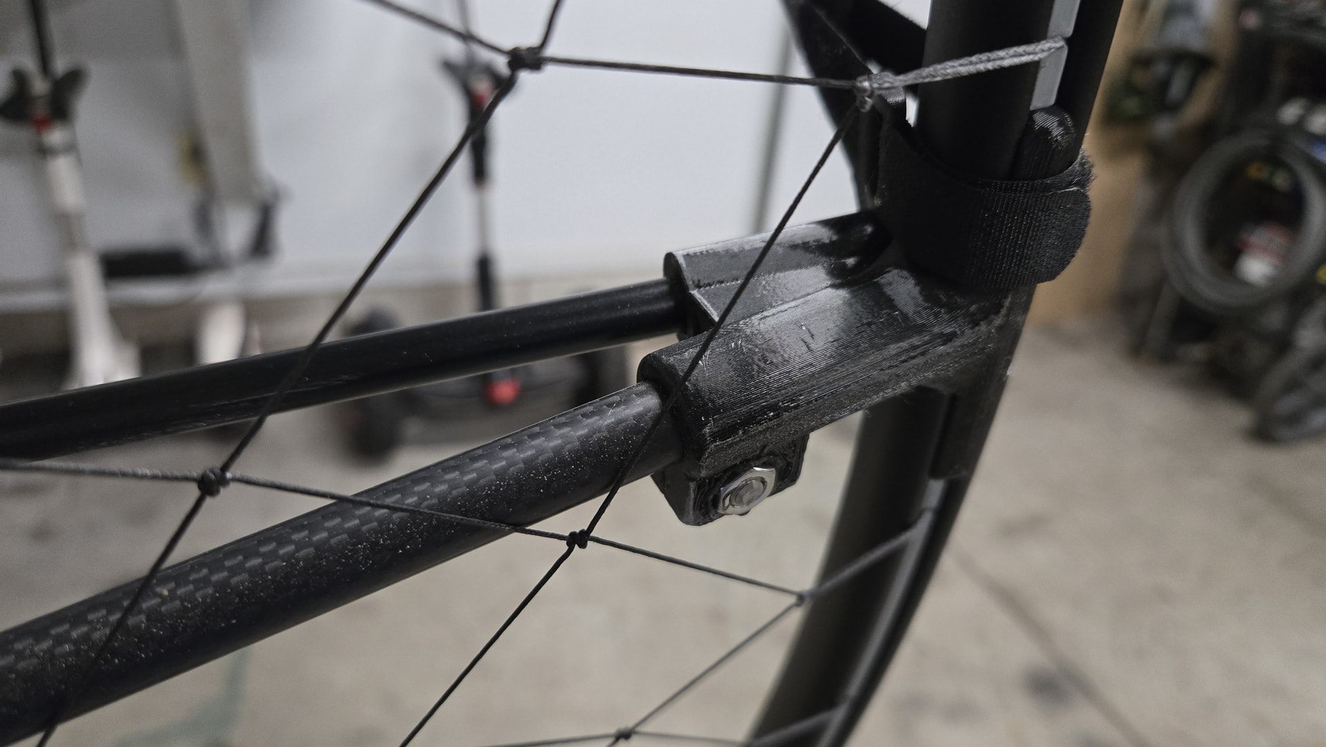
Hello Rick, agree with your thought process on stiffening the cage and think you idea/design is very solid. Can you please provide a bit more detail on how you modified the “T” portion of the connector?
I simply took the original connector 3d design and added the sockets for the cage rod and additional triangle stiffener and reprinted the connectors. I can publish them if you are interested.
Very nice, I appreciate the offer to share the file…yes please!
Here are the STL files as I modified. 2 and 5 have the sockets for the stiffener and cage extension, 3 and 4 have the cage extensions only.
sp140 cage connector for cage extension and diagonal brace.stl (3.2 MB)
Thank you kind sir!
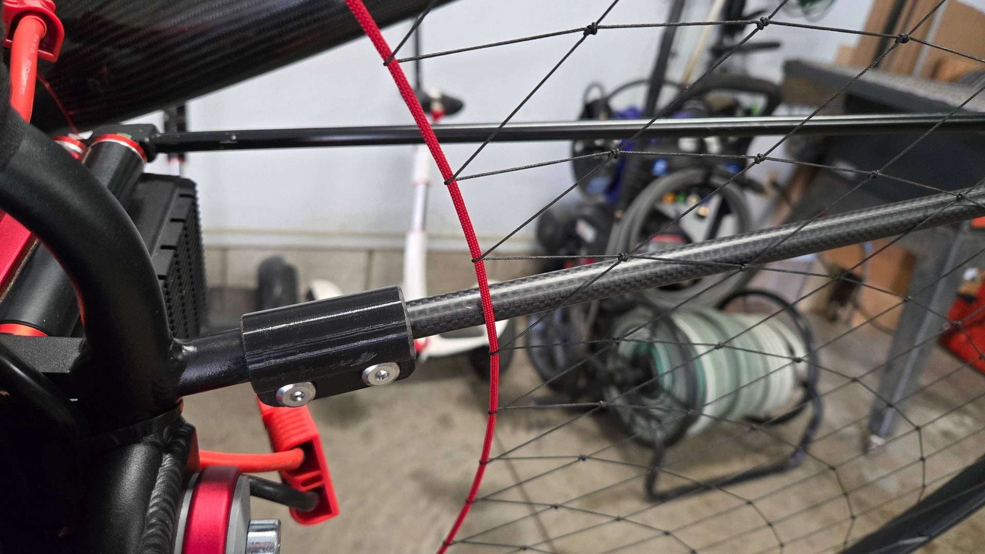
I’ve recently discovered that the diagonal cage brace I added causes the carbon fiber tubing to slip out of the frame socket on heavy pressure so I added 3D printed tube clamps that grip the tube so it won’t slip out. It is very solid now when pushing rearward on the cage.
Hi Rick, would it be possible to get more information from you on how you assembled the entire tricycle frame? Drawings, or maybe a model of the tricycle and all the parts? Thank you very much!
I’ve recently discovered that the diagonal cage brace I added causes the carbon fiber tubing to slip out of the frame socket on heavy pressure so I added 3D printed tube clamps that grip the tube so it won’t slip out. It is very solid now when pushing rearward on the cage.
Yes, I created a photo album with details about the trike I built. Look at the photos captions for info on each photo. I have used this trike for 3 different paramotors over the years, so look at all the photos to the end for various mods as time progressed. I’ve added many new photos of the 3d printed additions and cage entension/brace details. Tiny Trike 2.0 | Flickr
Thank you, I saw the photo album and since I have a health problem and can’t run with a motor on my back, I decided to make a tricycle on the SP140 V2.5. I just don’t know how to start and I really like your idea. Could you help me with that (of course for a fee), I’m from Europe.
Since I don’t make and sell trikes, you will have to rely on a local builder who can copy my design based on my photos and info in the captions. Several other builders have already done this with good results. If you need any questions answered or SP140 specifics, let me know.
I would need more detailed photos of how you mount the SP140 frame, what mount you use, what material your tricycle is made of, and what its approximate dimensions are. Thank you!
All basic dimensions are shown in the captions on each photo. How to mount the SP140 is up to the trike builder, I’ve adapted this trike to 3 paramotors, so if you have one built just for the SP140, you’ll have better options for mounting it instead of trying to duplicate my mount exactly. Your builder can provide guidance. I’m providing a basic design concept only. User assumes the risks of exact implementation. I’m including this better view of the trike attachment which consists of an upper and lower 3d printed parts that adapt the SP140 frame to the trike.
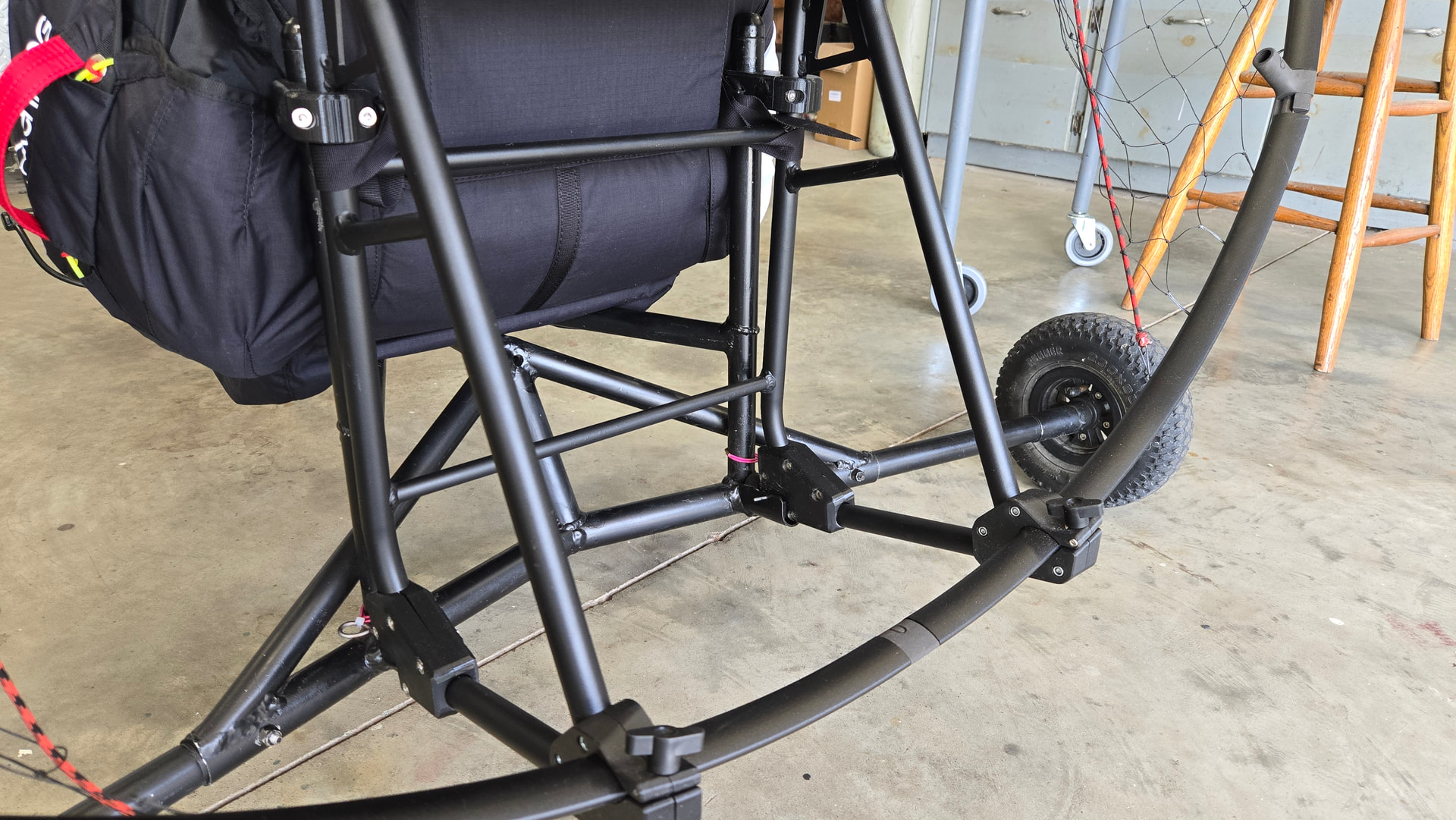
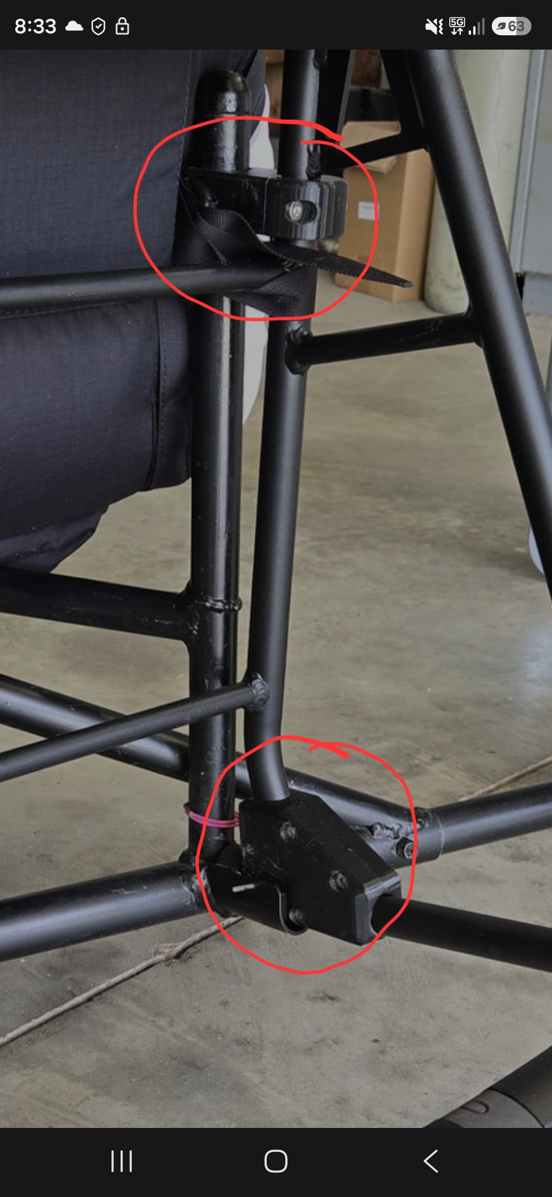
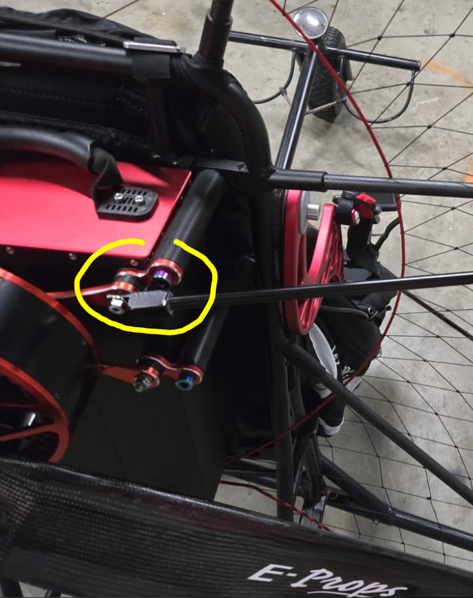
This is not a 3d printed part, it was fabricated from solid aluminum bar stock, sawed and drilled to accept the 3/8” diameter aluminum strut. Not shown is a set screw that holds the rod in the socket. I remove the set screw to remove the rod for the standard cage for foot launching and I permanently leave the fitting on the motor.
Thanks Rick for the explanation.
For anyone wanting to use my 3d files, I’ve modified these cage connectors to include carbon fiber tube clamps on #2 and #5 to prevent the backward pressure on the cage sections from pulling out, similar to the clamp shown above for the frame tube socket.