Hi Glider pilot I’d like to chime in, and say thanks for the data and the effort put into explaining this for the layman, I was worried about the battery Sag I noted during the testing of my Project and wondered if there was a better way of, if you like presenting the true-ish battery pack state , thanks to the data you presented, it seemed to mirror my newbie observations and you filled in the missing blanks for me , so Kudos To ya My Man and many thanks for the explanation 
Glad to hear that it was so helpful!
My Project started before Open PPG but some parallels in both worlds , so its great to get feedback and exchange ideas sincere Cheers to ya
Mad components just updated their website with motors and speed controllers. Are the kits supplied with mad component speed controllers if not what brand?
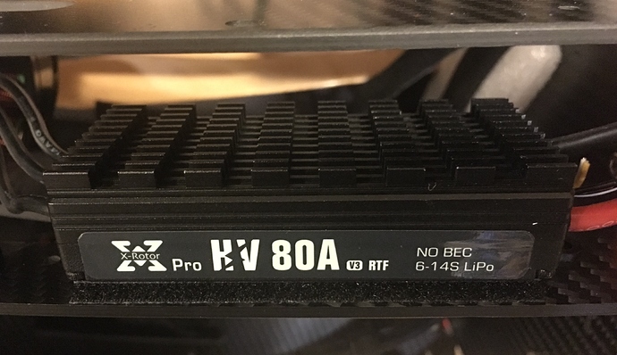
This speed controller has 120amp peak 80a continuous for 5-14s voltage.
They use similar cases but the components and firmware is a bit different, they do look similar.
At the cost of $40 and 200g more for 4: https://mad-motor.com/product/ampx-esc-120a/
I generally design my electronics to only hit 80% of rated components. I wonder for longevity we should be looking at these or trust that the protection circuits on the lower amp model does its job.
I’ve run my motor almost everyday for over a year now. I had one ESC go bad but I think the damage was from induction spikes. I added extra capacitors to each one and haven’t had any more issues. So far I think our system is pretty robust. Haven’t heard of anyone else on the forum commenting about ESCs going bad.
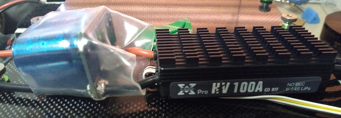
I don’t think either you need higher rated ESC’s. Except I will use 100A ESC’s because I use different prop’s and with 12S KV150 motors/23x13props and my weight I can reach 100A at full throttle…
I wanted 120A ESC’s but the ones with 7 capacitors are too height too fit inside where I put them.
I added to my 100A ESC’s (120A max) 5 additional capacitors and the 100A ESC’s have 12 awg instead the 14 awg wires from the ESC’s to the motors…
(Extra) capacitors compensate for (extra) battery side wire-inductance.
Their main purpose is to suppress voltage spikes higher than battery voltage.
Those voltage spikes occur with same frequency as controller PWM setting (8, 16, or 32kHz).
The capacitors operate as buffers between the battery and the ESC. The ESC switches on and off at a high rate. When it is On it presents a near short to the battery, causing the battery to try to supply very high current. But batteries have internal resistance so the high current will cause the battery output voltage to drop significantly. The capacitors are there to smooth out the current required from the battery. Capacitors can discharge very rapidly at very high currents. The battery charges the capacitor when the ESC is off allowing the battery to supply current at a lower rate.
Is this something that should be done on new builds as well? if if the wiring is short enough, we should be ok?
Gliderpilot wrote that as he used 6 packs at a cold day as he had that problem.
But he has 6 s not 7 s dont know if that effects anything.
It seems to be ok if you use 6 s with 4 packs not 6 packs at very cold scenarios.
You’re taking two issues and putting them together. I damaged some batteries on a cold day because cold batteries can’t handle the current draw. When I started using 6 batteries I had to add more wire length to the system. Plus the wires of the batteries themselves. Technically the wiring with 4 batteries is too long even if you trim your battery leads shorter. I think everyone should add capacitors.
Thank you for the info!
And sorry to mix your posts.
As there is only 1 switch in batch 4 becouse of 7 s use would you use 2 switches if you would build it for yourself?
With 1 switch there are shorter kables i think…
I will use the capacitors.
I did build a batch 4 for a friend and I used two switches. I like the redundancy. I like having only half the power going through each switch. I put a precharge circuit on one of them to protect the contacts because after the contacts get damaged they can’t handle 300 amps anymore. The way I wire 2 switches adds very little if any wire.
The US Occupational Safety and Health Administration (https://www.osha.gov)
considers all voltages of 50 volts or above to be hazardous. Not to scare anyone but
60 volts are just as lethal as 600 volt. I recommend everyone to use spark suppressor’s not only
to keep the connectors clean but to prolong the life of the ESC’s capacitors. With 12S voltage
the spark at connecting is already scary. Even more important with 14S. Like many people here
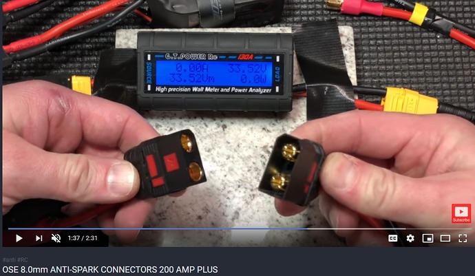
I use these:
Those connectors only work if they are used to close the circuit. Good idea to use them with the charger. But on the OpenPPG they won’t do anything for you unless you use the plug as a switch.
I thought the same…
We discussed this before. You can use the original switch only as an emergency disconnect if you
don’t have a pre-charge circuit. You will fry the contacts - which happened to owners.
You have to use anti-spark connectors to connect or use some kind of pre-charge switch!
With a pre-charge circuit you can use the original switch to connect. Or you can leave your switch on and
connect with the anti-spark connectors - same effect.
This is important and the correct information.
My batch 4 is almost together and the batteries have finally been delivered to my US shipping address for me to pick up. I went with 6s figuring I would not require the full thrust of 7s packs. I’ve been training on a Blackhawk 125 which advertises 131lbs of thrust. I wanted to save a bit of weight/cost and the charger options are better with 6s than 7s. The Blackhawk pushes 175lb me and my 22 square meter Buzz3 quite nicely.
So my question is: Will the Batch 4 150KV motors and 22X10 wooden props produce at least 35lbs of thrust each? If not my simplest solution would be 23X14 props but will that run the amps past the limit of the motors or ESCs?
You mean 22x14… I use 23x13 prop’s and have only 6-10mm space between the prop’s. I had
to reinforce the arms with more standoff’s and stabilize the cage. The arms originally twist and flex
15mm in all direction as well I had to modify the prop mounts and space the props out, so 22 inch prop’s are the save solution.
In my opinion just try it out with the 22x10 prop’s but expect more like 100lbs thrust with 12S.
The 22x10 with 14S and KV150 motors have the same thrust as the 22x10 with 12S KV180 motors.
One owner was on a real PPG thrust test and reached just short of 130lbs thrust. This is great since
the Paracell simplify reached with the 19KW single prop motor 127lbs thrust.
If you go with 22x14 props you could under full throttle and with full batteries reach 100A each ESC.
I use 100A ESC’s and use two power supplies. One power supply for the upper motors and one supply
for the lower motors to keep the amps halved. This works for me because I have 4 x 22000 mAh batteries and 4 x 16000 mAh battteries. If you split the power supply you can not fly with 6 batteries.
You see there are trade-offs. Batch4 was intended for 7S to lower the amps, but if you use it with 6S
and 22x14 props you are increasing the amps and need much more careful wiring.
Personally I believe the KV150 motors with 12S and 22x14 props are a great and effective combination
if you have the ESC’s and the right power supply wiring…


