Hi, can someone tell me please what material the motor plate is and how thick? It has to be one hell of material having a lot of holes but stil sustaining 90kg of force right in the center! I might have to build my own because I’ll be using the MAD 300A esc which is thicker (5cm instead of 3) that won’t fit between the engine and battery. So I’m thinking of mounting the motor directly on a plate that stays on the four 4 inch standofs and put the esc on one side. Bringing the motor 40mm closer might help with the angle in flight as I’m 150lbs, but will it bring the tips of the prop too close to the net? It seems prety far away from pictures. Another questin since I’ll have to buy the bolts, what grade are they including the ones in the gose neck arms, 8.8, 10.9, 12.9? Thank you very much!
for the last 20 eppg’s that i built i used most 8 mm gfk colored in black. this works even with motors up to 7 kg and a shaft power of around 18 kilowatts. for special light systems i used 6 mm carbon or 5 mm 7075 aluminum. all this has a very high proportion of additional strength. in my systems, all possible areas are milled out to increase the weight. partially not milled through but with gfk as an example only pocket millings with 5 mm depth at 8 mm plate thickness. for the motor screws i use normal 6.8 steel screws from 15 kilowatts (6-7 kilogram motors). 6mm for the standard or small motors up to 5 kg motor weight and up to 14 kilowatt shaft power I use titanium screws with 6 mm from the motorbike racing sector. The studs are turned from standard aluminum and have an inside diameter of 6.3 mm and an outside diameter of 15 mm. with the mad engine like the sp140 you can reach a maximum of 70 kg real thrust for a short time. therefore normal steel screws are sufficient.
Woow…20 eppg’s!  how many lives have you had? Bravo man!!
Hours pass by sometimes before I come up with a simple sketch on paper…
I might have found a company near by that can cnc/laser/water jet/plasma cut aluminum like EN-AW 7075, AlZn5,5MgCu, 3.4365,. Does this sound like a good material choice to you for the motor plate of the MAD M50 34kv 4,2kg motor?
Should I go for 5-6mm and a similar shape like SP140 or let it be more filled up with material? Danke Schon!

What’s gfk? Material you used
gfk in german " means " glas fiber laminate "
example:
Thanks. Didn’t even think of that.
Bratwurst do you have a link with aluminum sturds/standoffs. I only find with 10mm outside diameter and shorter than 100mm which is the lenght I need.
sorry i can’t help here. I’m a diy craftsman who makes everything possible myself. I can only recommend that if you are looking for perfect components and don’t have a lathe yourself, simply have the parts produced by online companies. there are now many companies in each country that specialize in small series and can deliver inexpensively.
Thanks. I’m thinking of making the motor plate from 6mm 7075 and the standoffs from normal alu bar of 20mm diameter, 100-130mm long (depending on prop clearence from the frame cage) and 120-150mm M8 bolts. Will this be to much/to heavy?
Is it normal for the motor plate to flex a bit under load? I’ve made the plate from 6mm 7075 alu aloy and on the floor on four woden bloks, under 68 kg load (me ![]() ) in the center, a similar thrust load to the SP140 M50 motor, it flexes 4mm. Then returns to initial shape. Maybe it won’t flex that much when mounted on the frame by the extra rigidity of the standoffs?
) in the center, a similar thrust load to the SP140 M50 motor, it flexes 4mm. Then returns to initial shape. Maybe it won’t flex that much when mounted on the frame by the extra rigidity of the standoffs?
Am I good here? I almost feel sorry I haven’t done smaler lightening holes just to have more confidence. Annyone knowing what’s the SP140 motor plate material?

From my point of view: a motor plate should absorb the forces generated by the motor through the large propeller. in the ideal case, the base plate is square like the petrol engine ppg. in the range of 21 by 21 centimeters to 25 by 25 centimeters. the motor center is in the upper area so that there is support at the bottom. If it is very wide like your motor mount, there will be a lot of movement of the motor through the pitch axis especially when running at full throttle. your plate will probably work, but unfortunately it doesn’t make much sense in terms of construction if you use thin material. if the material is thick such as 8 mm cfk you can of course also build wide motor mounts that are torsionally stiff enough.
What can I do now? ![]() I’ve worked so much at this plate…and at this project and not being able to trust the engine mount is demoralizing.
I’ve worked so much at this plate…and at this project and not being able to trust the engine mount is demoralizing.
What do you think about the SP motor plate?
It’s the same shape as mine, stays on 8 spacers and two rows of plates. Yes the plate is shorter but seems very thin. Mine is longer but also wider and maybe 1mm thiker and directly on the main spacers. Isn’t this enough to have the same resistence as the SP plate?
What would you do? Larger aluminium spacers like 25or 30 mm diameter, reinforcing the plate somehow?
If I use this plate that holds 70kg as tested and I will almost never use full throttle, in fact I might mechanicaly limit the handle to about 70%, what should I look for? Vibrations? Gradual throttle increase during tests to be able to shut down if vibrations apear?
you can use your plate. take aluminum 90 degree angle profiles with approx. 1 inch by 1 inch and 3 mm wall thickness and simply screw them together with the plate. the upper hole from the motor and the side ones to the frame. this creates a very good reinforcement. if you want to make it even better, you can glue the profiles to the plate with adhesive epoxy and it will be extremely stiff.
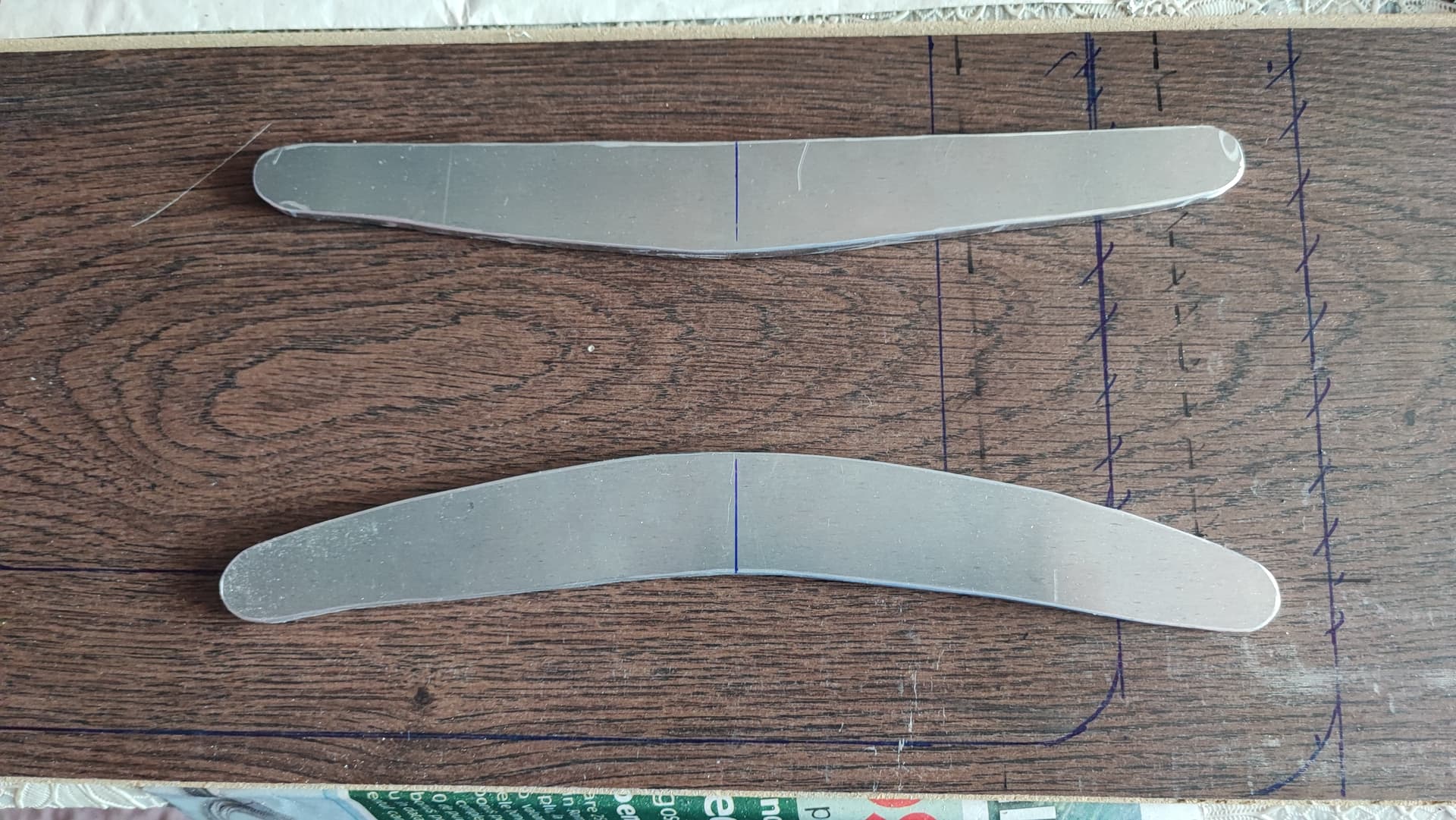
That’s very good news that I can use it ![]() I was thinking of bolting AND epoxy glueing aluminium profiles, one on the upper part, one on the lower part along the plates legs. Like in the photo.
I was thinking of bolting AND epoxy glueing aluminium profiles, one on the upper part, one on the lower part along the plates legs. Like in the photo.
Lukely I have about 3cm space left between the battery and the motor plate to put the profiles on the back of the plate.
Now I will have a pretty plate with lightening holes that is made heavier by reinforcements…remember that joke with the husband and his wife…![]()

After bolting the motor plate to the frame, at a 70 kg force on the motor it flexes only 1mm (see the pen in the photo) Is this acceptable or should I consider the 1.5mm alu corners to reinforce?
I haven’t find 3mm thick alu corners, only 1.5mm.
I wanted to reinforce with two plates of same 6mm 7075 material (photo below) but brings the weight of the plate from 325 to 550g!