I charged them to 80% for storage.
I think that heat from too much welding or soldering could damaged the liquide eletrolyte.
1 Like
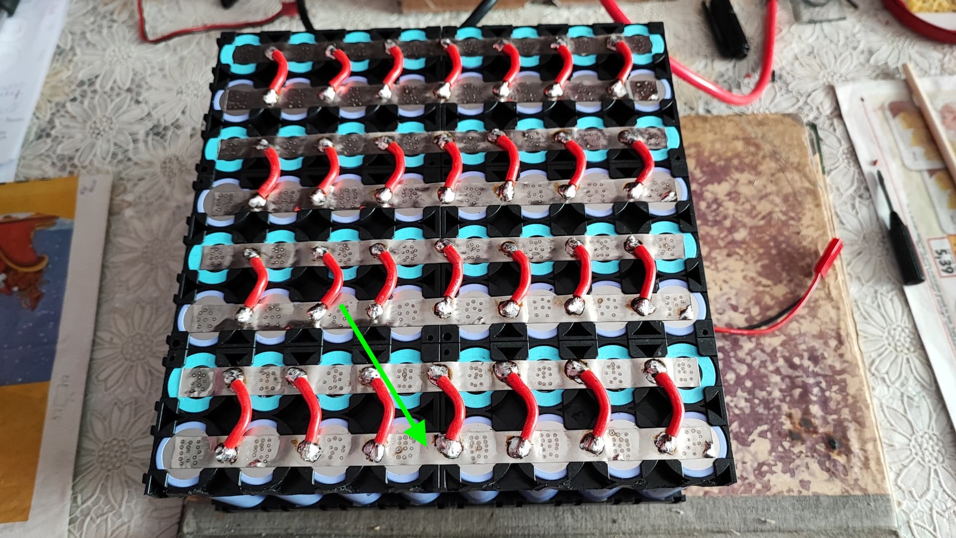
Correct that current does not travel much all in parallel, but to get to a cell it goes from your wire to nickel. 8 in series which means 17kw/100V=170A. 170/8 cells is 21 Amps that needs to go through that one strip to a cell. See the chart attached. I would mount a thermistor on one of the strips and check out the temps. Hard to guess now.
You wires are fine, its just that it can bee too many soldering points that ruin it for you. But this can only show when you measure the overall resistance of the pack and calculate theoretical resistance(without connections) of cells in 24s8p config.
Good rule of thumb, dont charge up the pack after flight, just leave it where it is. Of course you can charge it up to 80-90% if there is a high chance that you will fly the next day, this way you can be quicker up in the air!
1 Like
Roughly, sammy 40T have 10,5 milliohm.
10,5*24s/8p=31,5 milliohm for the total pack (excluding connections)
- Load current: 170 A
- Internal resistance: 31.5 milliohm (0.0315 Ohm)
Let’s calculate the voltage drop:
Voltage Drop = Current × Internal Resistance Voltage Drop = 170 A × 0.0315 Ohm = 5.355 V
So, with an internal resistance of 31.5 milliohm and a load current of 170 A, the voltage drop across the internal resistance would be approximately 5.355 V. but yours is 20,4V so it must be in your connections, this is a huge drop and not normal for this kind of configuration you have, you lose lots of energy due to losses somewhere.
1 Like
don’t believe everything some people write. 17 kw on the sp 140 for 7 minutes is absolutely impossible. neither the motor nor the esc nor the battery can do that.
2 Likes
You have built a 2.8 kw/h battery. you can definitely use them to make standard flights. with good conditions and a good wing you will certainly get longer flights in the early evening when the air gently rises over a large area.
you have learned a lot with your project so far and maybe in 1-2 years you can build a new battery with more capacity cells and more high-current capability. don’t focus too much on the actual flight time. enjoy your possible flights and you will have joy.
when i started with eppg 10 years ago i was happy for more than 10 minutes. today i never fly with the batteries empty because i don’t want to fly as long as it is often possible with a trike, for example. it is usually at the beginning that you put too much focus on motor runtime.
my best challenge is personally to use as little motor and more thermals (with pod concept and folding propeller). Enjoy your project and be proud of what you have built.
all the best.
ps:as far as your battery vallues is concerned, allex and comete have actually already said everything. so I won’t write anything about it here.
forget. with a three blade you can of course achieve a little increase in efficiency.
2 Likes
Thank you very much Alex for the graphs, calculations and everything. Thank you Komete. And thank you Thomas for the kind words! ![]()
Now I need your help further.
1.I’ve made the second flight, 22min because it was geting dark and decided to land. I’ve landed with 50% batt left, 16A from 32, 87.7v. and 41C batt. temp.
- I think that temp got down a bit because I’ve cleared all the fiberglass around the cells and made some holes in the batt case because I felt that they were in an oven. I’m curious what temp I’ll have now when going down to 30%left.
I know it’s suposed to be airthight otherwise the cells get different temp outside than inside, I’ve just felt like lettin’ them breath a little. If it’s wrong, or in the winter I’ll just cover the holes.


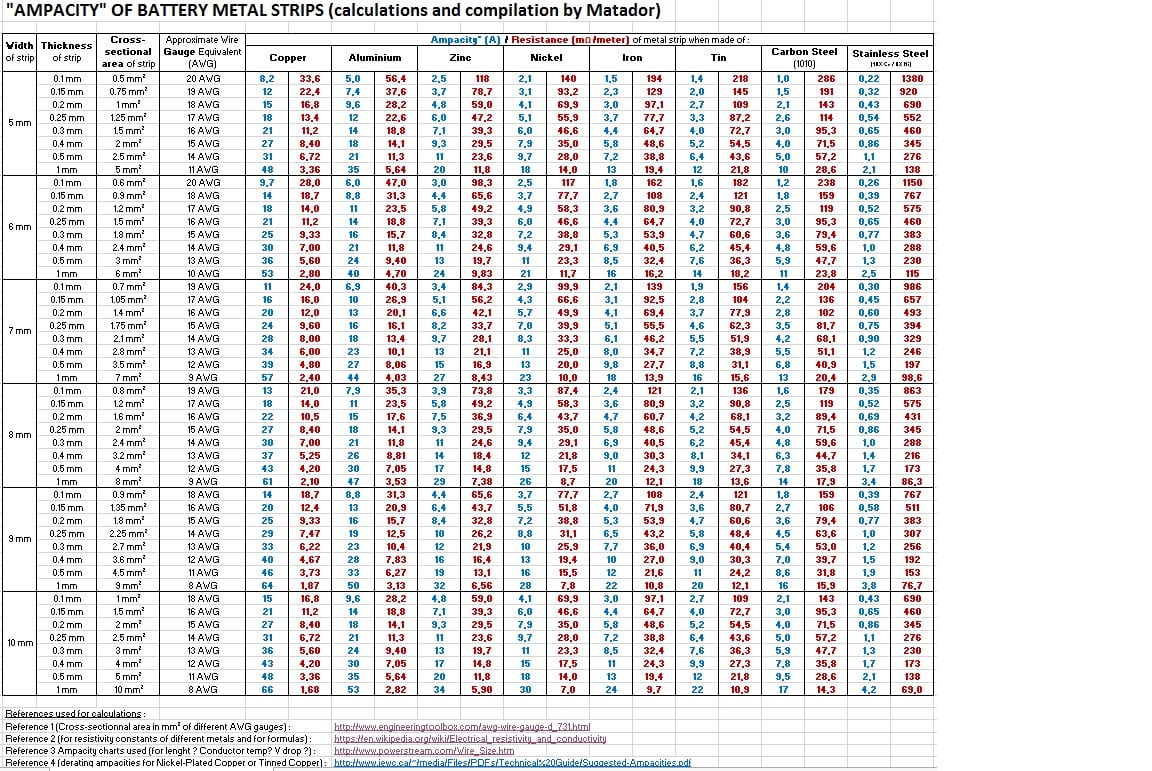
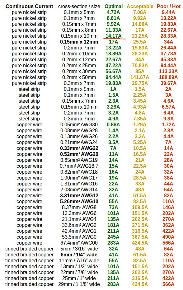
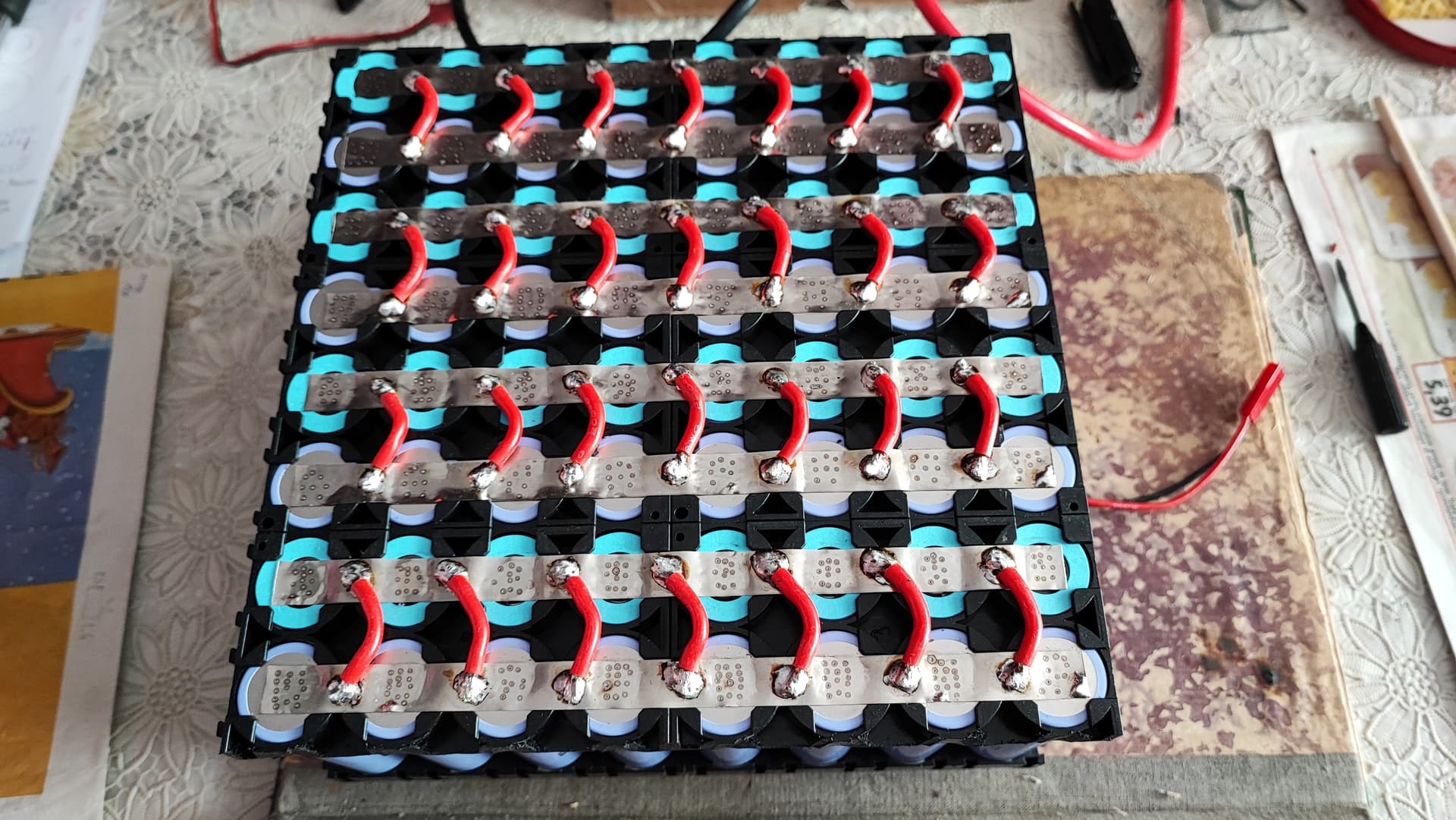
- Watching the two graphs of nikel ampherage I have a puzzle. For the 0.15x10mm nikel strip one graph shows 14A to be the best and even 21A acceptable and the other only 6A! See photos.
-
I’ll mount probe/s on the nikel inside the batt, any particular spot like on the packs ends or in the packs middle or it doesn’t matter?
-
These are new cells, I intend to use this battery so now the question is what can I do to improve the packs resistance? If I can keep the temp bellow 50C and get 27min flight down to 30% discharge from this 2.8kw batt, the only think that remains which makes me consider improving it is the huge voltage drop at full.
What would be the optimal solution and what would be the easiest one?
The cells are glued in the plastic cell holders otherwise the pack wobbled. The holder doesn’t allow wider nikel, and the 0.2x10mm is rated 7.9A not much from curent rating of 6A (0.15x10).
Don’t know how the welds are too, but removing nikel spikes from the cell is a pain, and removing the nikel strip with pliers or screwdriver I can’t even think how, in a short circuit so sensitive area. -
Would it be posible to just weld another layer of nikel or copper on top of the existing nikel, on the parallel groups, bending over the soldering points? It won’t be pretty but it’s the easyest way I can think of.
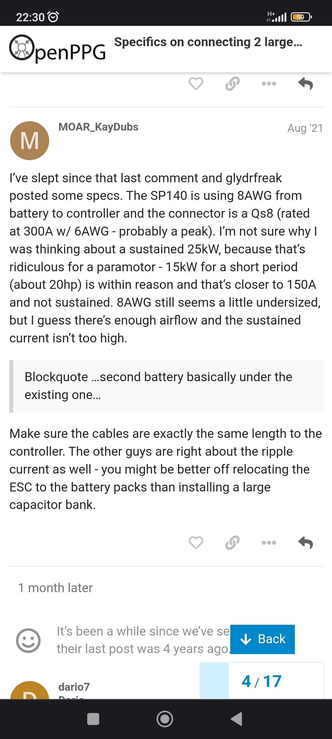
what is the cross-section (in mm) of the cables from the battery to the esc?
I use 8awg silicone wires like SP140 uses, it has 8.3mm2 cross sectional area, 3.5mm inner diameter, 6.5mm outer diameter.
I assume you only have 1 cable each for plus and minus? if that is the case, it is definitely far too low to conduct power over 12 kilowatts safely and with little loss over the long term. ( at 24 S ). in your case, since you use a motor that is in the maximum 10-12 kilowatt class, 1 cable per pole is enough. but point out that if you want to test e.g. 17 kilowatts of input power on the esc with one cable per pole, you will not get correct measurement results because the cable with awg 8 is too small.
1 Like
The SP140 uses a 6awg cable for reference.

ya haven’t used for awhile 6awg is what is used for the past year and now.
2 Likes
should be just an example of how I do it myself. applies to a 15 S system:
up to a maximum power of 10 kilowatts, i use 2 cables awg 8 per pole. so 4 cables.
For all larger applications, since I then also use 2 or 3 batteries, there are 8 cables or 12.
The adapter cables are all connected in parallel at the screw base of the esc.
1 Like
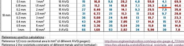
Reason for diff. values could be the length of the strip. In the xls attached I think they measure 1 meter of nickel.
https://endless-sphere.com/sphere/attachments/metal-strips-ampacity-resistances-by-matador-xlsx.252729/
For the probe, just put in in between the spot welds and solder point.
You can use wider nickel, just put it over the plastic parts. You could spot weld on top of the old one. But again, this may not solve your issue completely as you have lots of soldering points. See the temp first at full load before adding nickel.
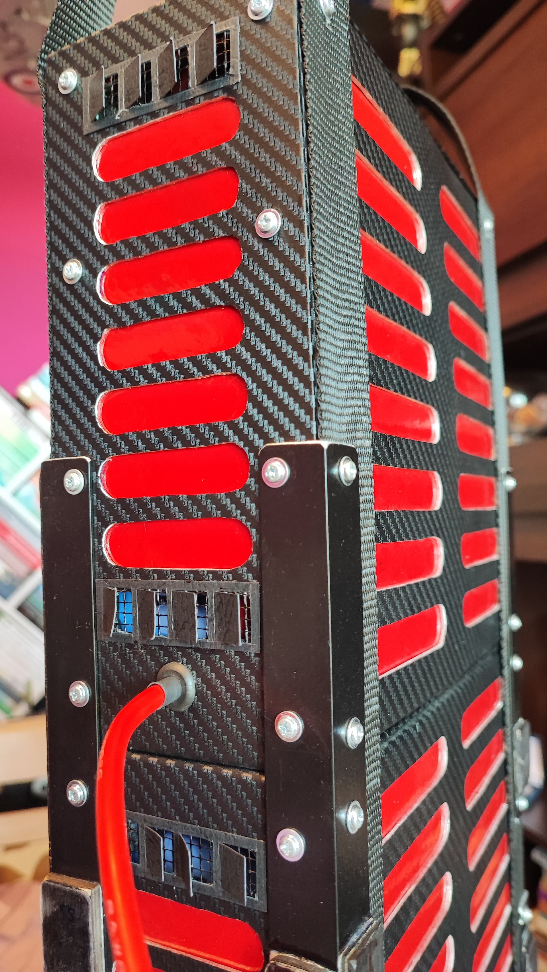
Is it solder here? Try to make a good crimp instead of soldering, it will decrease the resistance

(not a very good one but cheap)
Also I would try to use holders that are not straight as these but rather shift in hexagonal way. This way you will save a lot of space, pack will be much shorter. My guess that there is not many to find for 21700 and need to be custom made.
1 Like
Yes that is very good! I personally make the holders from fiberglass cnc milled. my friends who build e motocross batteries make the holders themselves from 3D printing in a plug-in system. so any battery size can be built. also works very well. But what we do differently is that we don’t do spot welding, we solder everything with copper circuit boards that are lasered from 0.5 mm copper sheet. but that is very special.