Hi, I would like to post my eppg project here. I’ve tried to find most of the components in Europe.
My project will not be dyi homebuild, but more like home assembling and the components are:
SP-140 frame and loop with netting.
MAD M50 34kw motor with 140cm prop and openppg prop quick release
MAD AMPX 300A 24S ESC (not totaly decided yet…)
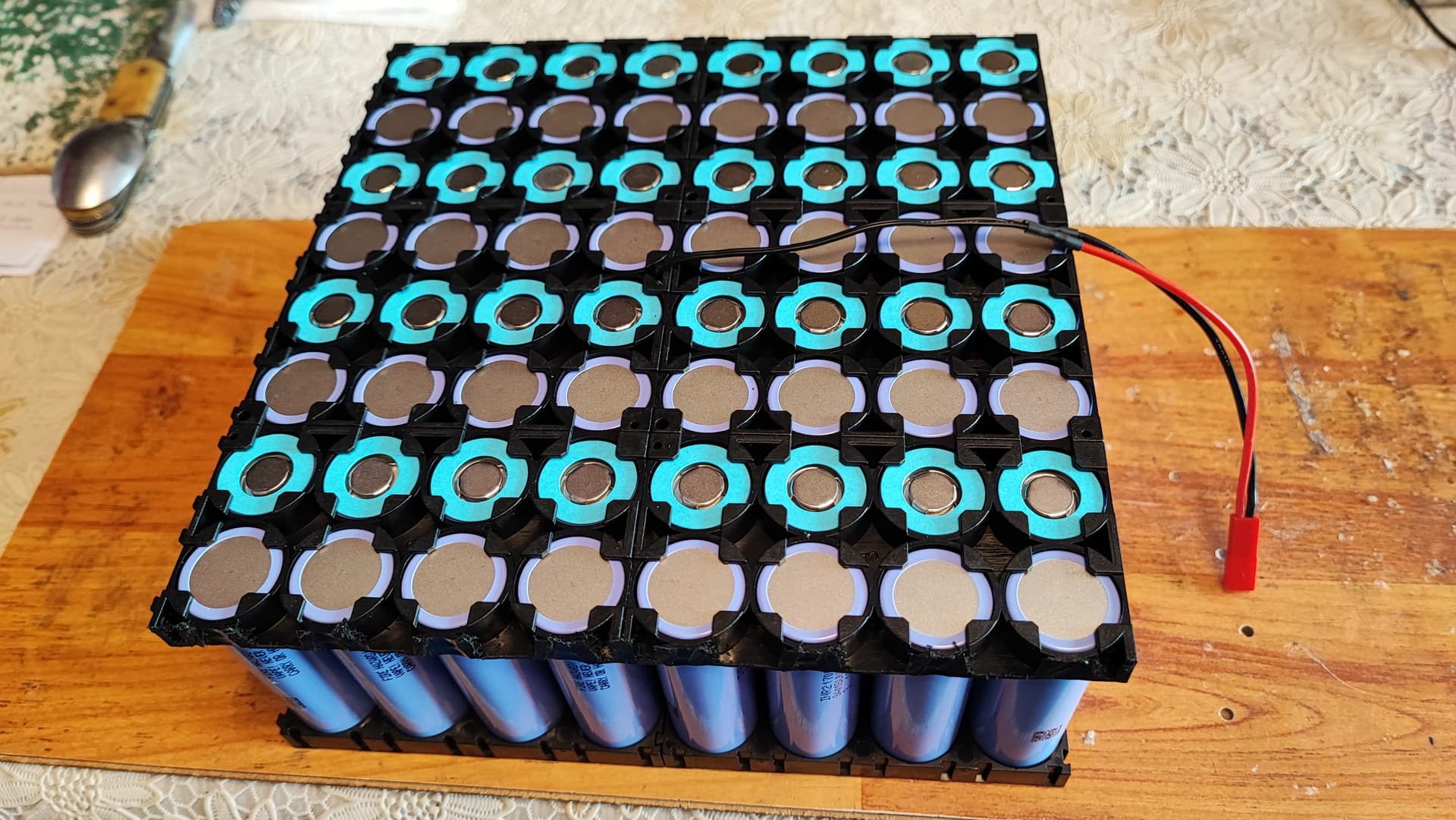
Custom made 24s 8p (2,8kw) li ion battery from Samsung INR21700-40T (40T3) 4000mAh - 35A cells.
Dudek comfort harness
Aluminium arms from Simplify (not sure yet)
homemade hand controller
custom made 20mm/100-130mm aluminium motor standoffs with M6 or M8 bolt through them.
custom made motor plate from 6mm 7075 aluminium aloy.
About the battery…
Because I’ve never built li ion batteries, reading through here about high voltages above 60v made me decide to split it in three and make smaller 8s 8p packs.
The individual 30v batteries will be each one in its aluminium case, separated one from another, with cables connected on the outside.
-I won’t be using an BMS, and I’ll be able to balance charge them with my ISDT T8 battery charger.
-Each pack will have a temperature probe in the middle, that gows to a 12V Temperature Controller that activates an alarm when a preset temp is reached, also I’ll be able to monitor the temp in flight.
-Each pack will have an xt60 plug for charging and an 8s balance plug to which I will have voltage alarm dispalys that will monitor the individual cell voltage.
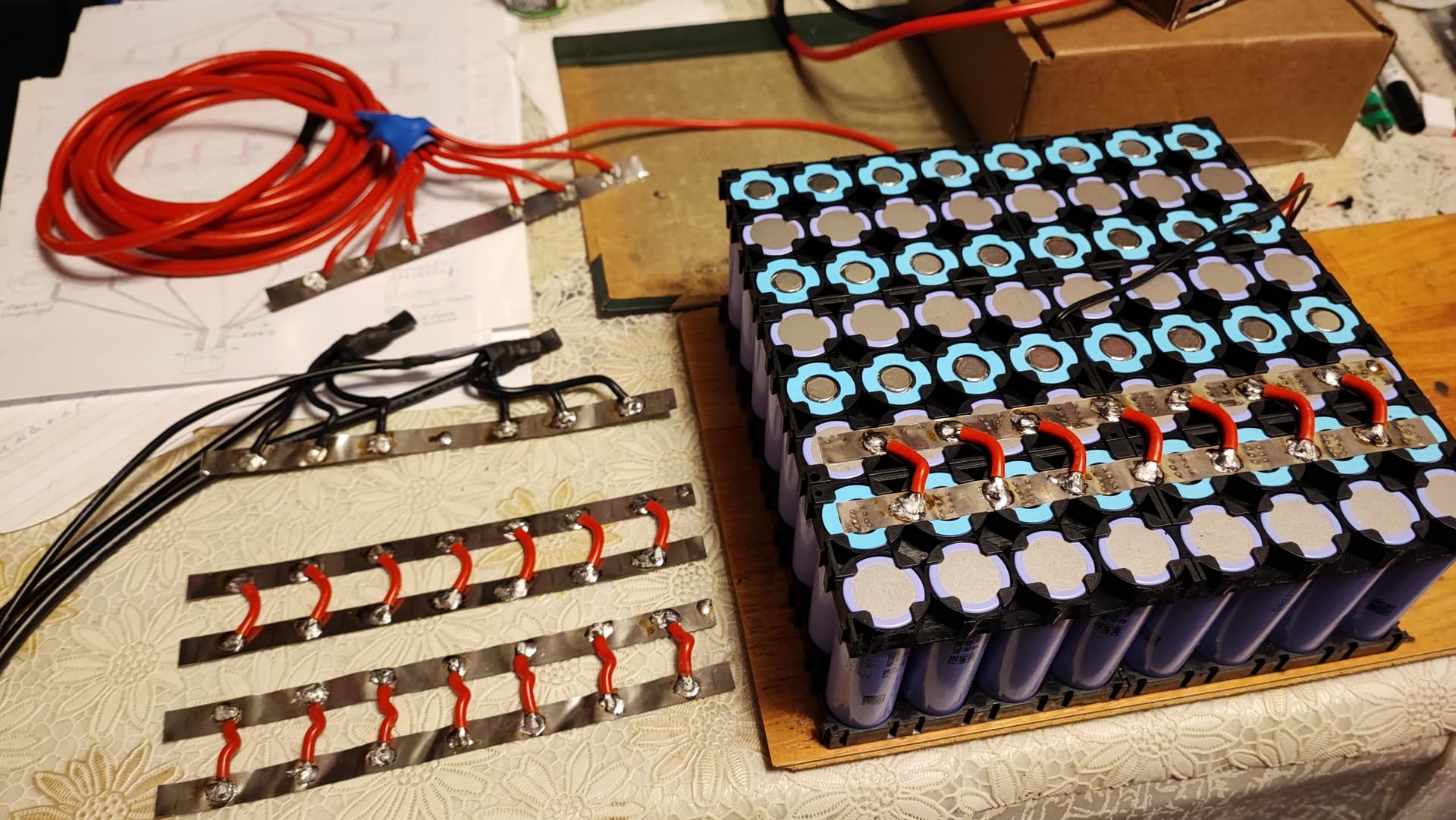
-The connections between packs like from the positive of one to the negative of the other I will have two 10AWG wires with same polarity going to both terminals of an xt90 connector so I think it will handle the amps.
-For the main plugs to the ESC I went for the AS 150 antispark that are rated at 150-200A. The reason for thinking they will be enough is that I’ll have consumption like 50-100A (4-9kw) most of the time and above that probably just for seconds…
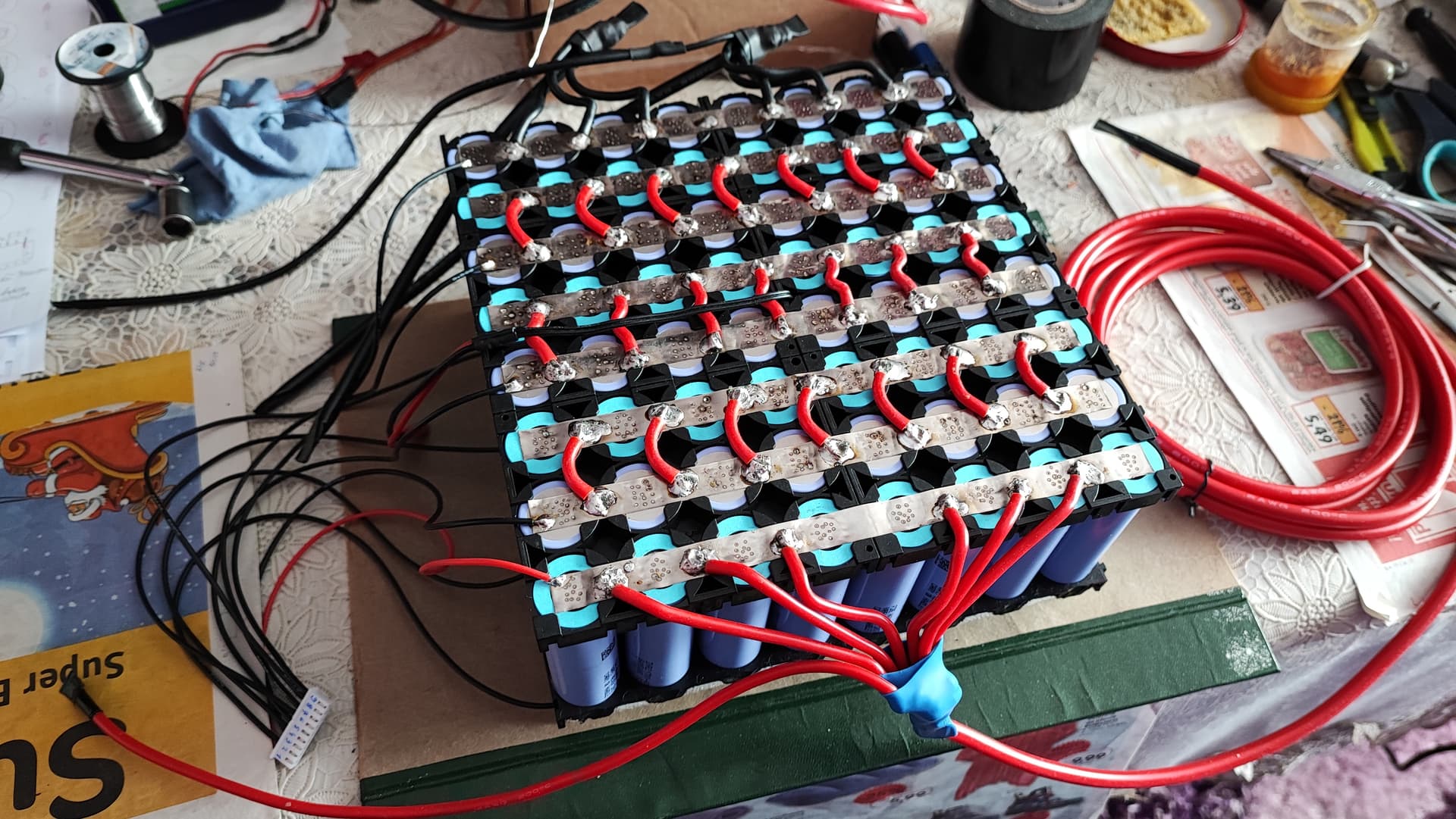
On the cells in paralel I’ve used one 0.15/10mm of pure nickel strip and between series 7 pcs of 14 AWG (rated 55A each) silicone cables. I’m also new to spot welding.
The alu batt case walls on the interior will be insulated with fiberglass and maybe some foam to secure them inside.
The reasons I went for a more complicated and with lots of cables three pack design:
I feel better knowing I’m working, and storing in the apartment smaller 30v li-ion batteries.
I can use my hobby charger which I’m familiar with and see very often the state of balance between cells on it or on the small volt dispalys on the batt case.
If something happens to o cell or a pack, it’s 1/3 of the whole batt not whole of it.
If the voltage of a group of series cells drops, the alarm gows on, if one pack overheats, the alarm gows on, in both cases I AM the one deciding what to do, if I need another 10 sec of power to pass an obstacle or turn into wind and land safely I’ll have it. Of course, I would land immediately.
The three aluminium batt boxes will be held together into one single battery by aluminium corner profile bolted along the four corners. Unfortunately, because the cells are in plastic holders and distances in the boxes, the total battery will be very long, about 62cm/22cm/9cm (the SP 140 has it at 48/26/9,6cm). But because I’ll have some distance between the frame and motor plate I’ll be able to recline it so it won’t hit the cage when handling it…in theory.
Any advice, idea and opinion are welcome!
Thermometer probe:
a nice project! a note. It would be good if you laid the cables that have more than 60 V with an orange hose or, better, orange cables. that is the cable to the esc and the cable from the esc to the motor. so the rescue workers and firefighters know what’s going on technically. also possibly make stickers that show the volts. It’s not just about whether there was an accident while flying, but also maybe a car accident through no fault of your own. everyone knows then through the orange color that one is careful. It’s just a safety tip. with many electric drives today, which often have 80 volts and more, it is now a problem for insurance companies how it is treated if there is no marking. a fireman who works as a volunteer has a shock in his heart because he only wants to help. that should not be.
that’s a good solution how you do it! in the automotive industry, fire brigade, police, etc., many helpers will be trained in the next few months. I noticed the currently “orange” cable which is synonymous with dangerous DC current. Hence my comments on this because it is becoming a standard worldwide - even the small e-motocross with 72 volts or more have now all been given orange cables, I just saw them a few minutes ago. sur ron storm bee and others in the scenne.
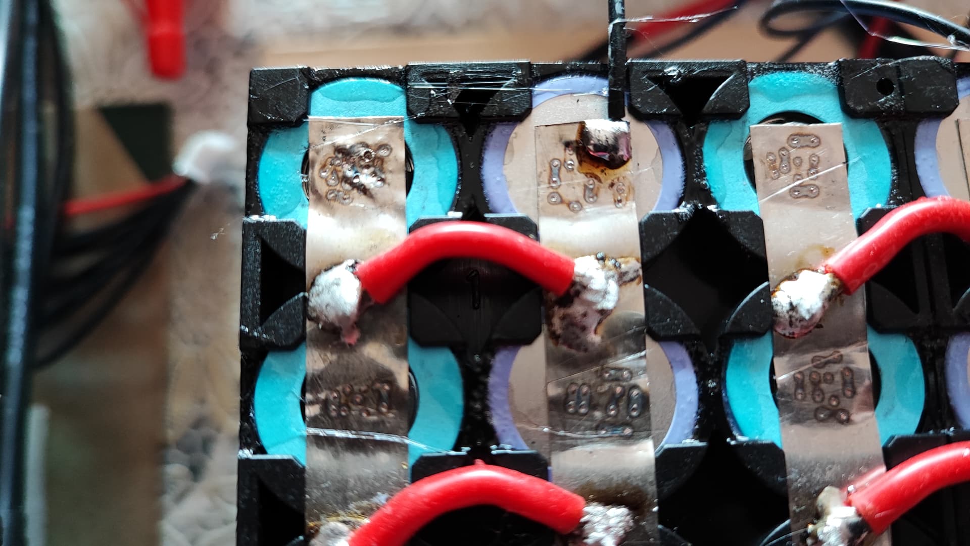
For the spot welding knowers:
I’ve noticed that some of the welding points look smaller and that they pop out when flex a smal screwdriver underneath the nickel plate. Then I’ve increased the power of the device beyond of step 30 which is not recomended with a new max.45A car battery, and I made other welds. How can I check them without detaching the nickel because I have no more space on it to make new welds…but It gives me a feeling of insecurity not checking them… Of course I’ve practiced on spare cells, different power levels, and most of them were good. Thing is, if you press too hard the welds are weak, I’ve seen it on youtube more people sayng that, then I start with very gentle press and I had somme blow up burned holes through the nickel and sparks that freak me out, I’m guessing because was no contact between the nickel and battery from not enough presure. Although I use a hard, rounded woden stick to force the nickel to lay on the batteryes because the plastic holders together with the ring caps and the fact that I’ve soldered the wires so I won’t heat the batteryes, made the nickel not to lay perfect on them, but after cleaning it and force it down it stays down on them.
Don’t know why my copper wire electrodes get blunt after ten welds either…articles say too much courrent, how the hell is too much if it makes tini welds that don’t hold…
I think I’ll check some of them with the screwdriver, make some more welds if needed at level 50 from 99 and see…then I’ll put some hard foam in rows to press on the welds when I’ll wrap the battery in shrink tube to hold it together. And that’s it. Not a fan of this spot welding…I might have to change the electrodes after making one battery that’s how short they got after so much sharpening. And the new 44A-390A car batt gets from 13v to 12.6 after welding one side of a 8s8p pack…
Moving on with the project, battery is done, now it’s time for the batt case but I had to learn to bend aluminium at 90 degrees first… I’ve made lightening holes, not towards the pilot or up. I had to do holes because aluminium is not as light as I thought and didn’t like how heavy the three boxes turned out. The holes will be covered on the inside by a nylon foil then 4-5mm thick fireproof ceramic fibre cloth around the battery, and foam to secure it. And since I was advised that airthight is the way and not having air flux over it, the battery will be wraped in heat shrink wrap to make it even more robust. And the wrap will protect agains ceramic fiber which is kind of sandy like fiberglass.
I had to glue each cell into the plastic holder because otherwise all the pack would bend when lifted, holding all that weight only by the nikel strips, that’s a no,no. Now it’s brick rigid. The boxes will be bolted one on top of the other.
The reasons I went on making the battery myself is customization, price, learning about making battery paks.
Most folks that get into PPG for flying is cost. It is the lowest cost, not cheap, but lowest cost of flying. When moving to electric, even in the Electric car market, the batteries are still the most expensive part of the vehicle. No difference here.
When I convert my Flexwing to E I have no reservation admitting, that for me, making my own packs will be for cost saving alone, as I have more time than money.
If I can save 40 to 50% on making a battery while sitting around during a long winter, so it shall be, even if it wont look as '“professional”.
Yours is looking very nice IMHO.
Safe landing to all.
Cheers
Thank you E-pusher!
Just finished the batt case, lightened it as much as I could…is 2,3kg. 65/22/9cm…a litle long due to batt holders, and distances between the three packs in series but hope it fits.
Some photos with it and other godies, just received the prop, it’s grandioso!
Just finished the first layer of insolation/padding on the batt interior.
Received the motor standoffs made by a skilled craftsman on a lathe and I’m amazed by their precision. I’ve decided to make them 13cm so that the prop tips will have about 9cm from the frame, that’s what felt right. First I’ve tryed 12cm with a block of books but at 8cm from the frame minus two that E-props state it flex towards the frame seemed to close. I wanted to mount it as close as I feel confortable for the prop distance. Although the closer the better for my weight and hang angle.
Next is the six mm 7075 aluminium allow motor plate, this thing is taught! I hope it will stay hard enough for a 70kg motor force after I cut the lightening holes.
And first charge of the battery came along with one concerning… first cell (row of 8 cells) has an incredible high impedance compared to other cells (see photo), it has 5 to 6,3 mohms ant others have below 1! And it has slightly less voltage of 3,70v and other cell groups have 4,75v. But as soon as the charging started this cell jumps to higher voltage than others, see photo, and at the end of charging it has less again and the charger takes one hour to bring it from 4.08 to 4.10 as others are. (4.10 is the standard end voltage for li ion in this charger).
Wat does this mean? And on all three packs the same cell group!
Because I’ve connected each pack individualy to charge it, each 8s8p (30v 32A) and on each pack the first group of cells had about 18 mohms while the rest had 1,7 - 2,5 mohms.
Can this be a wire resistence?
Battery specs: 192 pcs of new lithium ion Samsung INR 40t 4000mA, 35A cells in three 8s8p packs. Charged them in paralel at 15A(5A each) with an ISDT T8 smart charger and a paralel charging board.
Every cell was check when bought and had 3,44v.
Is it dangerous to continue like this or should I dissasemble the packs and see?
hello, what i see here is known in many areas of e-mobility. if you use some chargers at the performance limit, the 1st channel or the last one (no. 8, 7) is always wrong with regard to the measuring current, balllancer. I haven’t found out why after 8 years. also no manufacturer of the rc charger can say why. I suspect that the x-fold capacity and high performance of the eppg packs caused the error. because if you charge the same aku with just a few amps, the phenomenon does not occur. at least the cases that I know myself from friends and my own findings. In any case, there is no problem, for example with 5 S or 6 S batteries. it’s always at 7S or 8S packs. The charger is special, the 7 or 8 S with full load have errors in other programs, for example. Nimh or lead batteries work normally. it can also be that the resistance of a balancer cable has a bad connection. you can check that with a meter.
Thank you! Happy to hear that. Today my 220v 2500w infrared heater arrived to be used as a load for storage the pack when charged and not flown for any reason. And made the first fully charge and descharge cycle from 98v to 87v in 3,5 hours (I’ve choosen not to go further for now). At a load rate of 390w at the start then droping to 300w as the voltage droped.
After discharge, with no load the cells, with a meter had between 3,66 - 3,68 except that last cell of each pack that has 3,62v. So it’s not just the charger?
Is this a big difference to be concerning? Will they ballance in time with more cycles?
I see a potential problem… and that is when you will be looking up at your wing during inflation forward or reversed - your helmet may bump against the pack. Can’t say for certain, but that something you will have to check during an actual run. Your cage/hoop will be tilted forward in a forward inflation and your head will have to look straight up or even slightly backward to see if the wing is okay and fully inflated. The same will apply for a reversed once the wing is overhead. Just a thought!
Yes indeed if I tilt the head bach I hit the battery, if it had been only 4cm shorter/lower …but if I look side to side up I don’t hit it. Some ground testing with the wing will answer if it’s doable or do I have to change something like lowering the battery but don’t know how…
It’s nice in the back, doesn’t feel too heavy. The batt is 17kg. It’s like having three bonkas lipo just it’s lithium ion, each one with a balance lead and power lead, mine have also separate charging leads. Anny way I like the way it looks and don’t feel like destroing the case and start from scratch…I hope I can fly it like this, at least I would have a head rest I will have to learn to run body lean back, head down
It looks like an ejecting seat
As long as you have problems with the voltages of the individual cells, I would only do performance tests on the ground with real power and constantly check the voltages and check them thermally. Personally, I wouldn’t fly if a battery is positioned so far up there. see here only disadvantages and no advantage. even a danger to the pilot’s neck in the event of a bad landing.