Then after this degugger output, the U-Vision says failed and has the following error output.
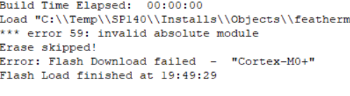
Then after this degugger output, the U-Vision says failed and has the following error output.
Daily Update until I get this controller working.
No progress on flashing the bootloader. I am convinced the flash download is failing because the BootProt fuse is set on the chip. Curiously enough, if the bootprot fuse is keeping me from flashing a new bootloader then I would think it should have also prevented me from corrupting the bootloader to begin with. But yet here I am. Im switching gears to try and figure out how to just load the existing project into the controller over the SWD pins and abandon the non-working USB port and bootloader.
I’ve downloaded VS-Code, Platform I/O package, and all the library and source code from Github, but for some reason my project doesnt build. It had two errors for missing library for barometer, and the circular buffer, but even after I imported those librarys it still fails but no longer gives me any errors with the code. The X4 code builds just fine.
Im a noob at VS-Code so I could use some help here to figure out why the code isn’t working.
The next issue I have is that even if I were to get the code to build, it will generate a .Bin file, but my JTAG/SWD programmer needs a .hex file to flash the controller with. Anyone else going through this JUST GET THE PROPPER J-LINK!!! If I had that it could flash the .Bin file directly, but the knock off U-Link needs the file in Hex. I also need help figuring out how to export the project from VS-Code as a .Hex file. Or how to convert the .bin file to .hex. Though I expect that to be a whole other can of worms.
I guess another option would be to buy a fresh board ( with functioning bootloader) that has the ATSAMD21G chip on it and attempt a component replacement. But this seems extreme and I don’t want to modify the hardware to fix corrupted software issue.
I’ve resorted to asking on Facebook if someone can loan me a controller for the BA fly in this week. If anyone here has a working controller they wont be using next week and is willing to loan it to me. PLEASE! I’ll cover all shipping costs next day air to me and then back to you. I’ve inquired with Zach and Paul if they can sell me a new one at cost. I am open to any ideas but I gotta figure out a way to get a working controller by this Thursday.
I wish I had better news here but this may help point you in the right direction.
I use the segger jlink to flash the initial bootloader when it comes from the factory.
Its unfortunately out of stock everywhere, even the edu version. I dont even have one currently to send.
Here is the repo you can build the bootloader from with some instructions. You can just use the standard adafruit feather since thats probably simpler than using our forked version thats slightly customized
With all the supply chain issues, we dont have any extra controllers (we sent our extra extras out a while back)
Our new controller isnt even using the same SAMD21 chip, mostly because it doesnt seem to be in stock for a while (more to come on new controller soon).
As far as the firmware hex file, the Arduino ide builds it automatically. The last supported release has the .hex file attached Release [SP140] Power calculation updates · openppg/eppg-controller · GitHub
I found that this may work and they have a few left in stock so just ordered a couple to test.
Docs are here if you want to experiment with me
https://docs.particle.io/datasheets/accessories/debugger/
Hi Zach,
UPS shows my controller delivered. Please post an update with any findings when you have a chance to examine it.
Thanks
Update: so I have figured out the u-link programmer and all the configuration and settings and stuff. I was able to load the compiled .hex file for the 5.3 firmware. But unfortunately the controller is still dead. I’m guessing there still must be something wrong with the bootloader that is preventing the code from even running. No LEDs on the board when plugged into USB, no drive recognized. When plugged into the paramotor, the green LED2 comes on with power.
Finally got the debugger delivered and was able to revive your controller @cwsnyder2001 !
It took a few commands and it seems like everything is working so far.
I restored both the bootloader and version 5.3 of the firmware separately and then updated to 5.4 via the .uf2 drag and drop and it all worked as expected. Not sure what the issue you had was!
I’ll do some more experimenting and then reach out to return it to you ASAP.
Thank you for your response and evaluation.
The only thing I made of been doing was switching between the battery and usb many times (20 to 30) without dismounting the usb but no one has mentioned that being an issue.
Awesome news! Hope to be able to revive mine soon too! How were you able to unlock the bootloader protection?
There shouldnt have been any bootloader protection and I didnt do anything special. I just used OpenOCD to flash the files like normal.
I can put a tutorial/screen recording together. @jsneeb are you on Mac, Linux, or Windows?
Got it working on Mac & Windows so far.
I would appreciate/fund? a tutorial. I would like to continue to investigate software changes and I need the confidence that if I brick it again, recovery is possible. My environment is Windows.
Cool, I should be able to get that put together tomorrow soon
I havent had a chance to be back in front of my Windows desktop to do a screen recoding but didnt want to leave you hanging.
In the meantime here are some directions on what worked for me (should be basically the same on all platforms)
This will be similar to what Adafruit describes here
We’ll want to download their config file from here.
You’ll want to download the OpenOCD software. The easiest way is to download the prebuilt binaries from here Releases · xpack-dev-tools/openocd-xpack · GitHub
Once you unzip that just put it in an easy to remember directory.
Do the same with the bootloader file Adafruit-Feather-M0-Basic-Proto-PCB/featherm0bootloader_151101.hex at master · adafruit/Adafruit-Feather-M0-Basic-Proto-PCB · GitHub
and the firmware file
https://github.com/openppg/eppg-controller/releases/download/v5.3/eppg-controller.ino.hex
Attach your OpenPPG controller to the SWD connector using the ribbon cable. Plug in the controller to USB to power it up and plug in the flashing tool to USB on your computer.
Open up a terminal window and navigate to the unzip OpenOCD folder from your download and go to bin/ where you’ll see the program (eg openocd.exe)
For using OpenOCD tool to flash microcontroller you’ll first want to connect to the micro controller by running the openocd program with the specified config file for this specific chip that you download from the adafruit github
$ .\openocd -f arduino_zero.cfg
You should see some output in the terminal that its detected the chip etc. If it keeps spitting out more info then its probably still trying to connect.
In another terminal window youll need to actually connect to the debugger chip by running
$ telnet localhost 4444
you should see a prompt that you are running in the on-chip debugger
In the new telnet command prompt run
> reset halt
next we’ll flash the bootloader with
> load_image featherm0bootloader_151101.hex
It should show that it successfully wrote a number of bytes to the memory. Technically at this point you should have the bootloader on the controller and be able to double tap reset to go into the uf2 mode and paste in the latest .uf2 file, BUT we’ll just flash the firmware file in the same way because its already set up.
> load_image eppg-controller.ino.hex
now the last step
> reset run
Congrats, you should see the controller boot up like normal.
I realize this might not be the best directions and usually a screen recording is easier to follow along, so I still plan on doing that ASAP.
Thanks! That is a great write up and it seems the only thing I was doing differently than you is that I didn’t have the right ribon cable. ( So i just made a temporary pin on a wire for the 4 necessary wires ) and that I was using a U-link programmer an U-vision rather than Open OCD and ACC debugger.
Thanks also for getting me a spare controller in the meanwhile so I could fly at bad apples!
Have you managed to do a tutorial video for this yet. This is the exact problem I had with my original throttle controller. I purchased the debugger from Mouser that you linked to. Otherwise I’d like to send my throttle to you and have you do your magic. I’ve tried all fixes mentioned in this post and none have worked. Also purchased a new throttle and all I’m getting from it is battery error, no motor response.
nah sorry. I got as close as being able to talk to the controller via the Ulink, But it was not able to write a bootloader file to the protected memory portion of the controller.
I think I was going to deep into it. I had OpenPPg replace my controller with the 5.6V firmware and now I have left it alone its been fine.
Good news, the mini is now back in stock from Adafruit
Supplies might not last long. Handy to have if you’re into developing on these types of Arduino boards
Is this similar to the debugger linked above from Mauser?
I had the same issue as @jsneeb was showing in his video. Only the blue LED was on, when it was connected to the esc.
I also followed the instructions @zjwhitehead gave using the Particle Debugger. From the Terminal output it seems like it was at least successful to load the images, but unfortunately it is still dead. Here is the terminal output:
Bummer, I was never quite able to resolve the issue but I felt like I got pretty close. I ended up trading my bricked controller for a working one from Paul
