I am trying to figure with power rating for my registration application
My answer to that question was 16 kW in total. i measured 75A per motor controller steady state at 50V. I measured mine with a LEM HASS-50 and watched the values on an oscilloscope
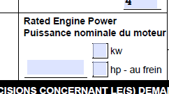
i did 18.5kw - 48v X surge of 384A
I think if I was making a registration application I’d put down 16kw with the confidence of knowing that the registration authority would have absolutely no ability (or interest) of proving you wrong 
Paul-Oz - Based on your statement, then it is ok to put just about anything that is within the ballpark.
but maybe there should be a standard rating listed by Openppg in case the authorities go to check.
Cheers
I had a bit of time to play more with the unit tonight. Here’s what I learnt:
The range of PWM (go signal from throttle) is quite wide - more so than my servo tester so I did a throttle calibration. The response range now seems better.

I also changed the ESC timing to HIGH. The motors now run much smoother through the throttle range. None of that ugly resonating (phase mis-firing) that was happening at mid throttle on the INT default setting.
Here’s a link to the document that describes how to do this (different model, process the same):
http://www.hobbywing.com/products/enpdf/xrotorpro25acircular.pdf
Note - you will need separate 5 volts to power your throttle as you connect battery under full throttle to get into these modes.
I’m still trying to find a more elegant solution to attaching the batteries. How are you guys doing it?
5 Likes
Great info - thx
cheers
Thanks for the information Lukas! I wonder why the instructions that came with these ESC’s didn’t have these programming instructions.
When you say you did a throttle calibration do you mean on the ESC using step 2 in the link you provided or did you do some programming on the throttle controller itself?
It says intermediate timing is more efficient and produces less heat but if high timing makes the resonating go away wouldn’t that be more efficient and produce less heat?
Do you think it would be possible to program all 4 ESC’s at the same time so I don’t have to take the back plate off to disconnect the others? Is the reason we need a separate 5v so that you can power on the throttle controller before powering on the ESC’s? What if I just held down the throttle all the way when turning the switch on, would that put it into program mode? I thought the extra leads on the ESC are for programming but we don’t need those for this right?
Sorry for asking so many questions. I’ve programmed RC ESC’s before but this is a just a little different.
Just to chime in that you could program the throttle controller to do the ESC calibration for you all at once. However I havent had time to look into doing that and it would take some testing.
If someone wants to do it then throw the code up on Github Id be happy to take a look and integrate it.
Yes. All 4 ESC’s done at once. And yes. Throttle range calibration as described in step 2 of above linked document.
The additional 5v power is artificially injected into throttle/hand-switch. It needs to be powered up, armed and at full throttle BEFORE the main power is supplied to the ESCs. Listen for those beep codes then release the throttle at the appropriate time. No programming leads or re-plugging of the ESC’s needed.
Try both of the timing settings and go with the one that SOUNDS the smoothest throughout the range. I’m curious to her other feedback.
1 Like
What did you use as the power source and where exactly did you plug it in? I’m guessing that I can’t just run power through the USB on the bottom of the controller? I assume I need to unplug the controller from the BEC and plug it into a separate 5v source which will require me to take the back plate off the motor to gain access.
Thanks!
I think your right with plugging into the USB in the base of the throttle,using just a phone charger. I just tried it and it armed OK.
That’s all you need. Armed - Full throttle - Main power on - listen for the beeps. Let us know if it worked.
1 Like
Here’s another idea I’ve been working through regarding attaching the batteries to the frame. Lets see what breaks first…
3mm Perspex riding on 10mm brass stand-off’s, screwed into the 35mm stand-off’s inside the frame
I plan on using sticky velcro on the batt’s and perspex. Also Velcro straps through the frame to lock it all together.
Hoping to make field assembly of the battery a bit easier.


In my dreams, I’m a CAD god with my own CNC in the garage.
In my dreams the batteries ride in a carbon, tabbed box that interlocks with the frame.
In reality, I’m hacking at perspex with a dremel and a marker, wondering what time the pizza shop opens.
7 Likes
Lol, you must be my brother from another mother!
Cheers
1 Like
I’m struggling with how to wire the power connections on mine and I like what you have here. I see some discussion further down about those bus bars not being sufficient. Have you actually flown it yet? Do you see any problems?
Where do the batteries connect? On the left side of the photo? I’m imagining that you have two batteries in series, and then connect into the switch on the + side and the other bar on the - side. Repeat for second battery pair. Where would the controller power connect? On one of the free terminals of each block?
I have decided not to go with the Bus-Bar connections - though they look nice and neat and would most likely handle the load; I had some concerns moving forward.
My tipping point was that i wasn’t happy with the ways I tried to insulate them. They ended up big and bulky, but also very serious consequences if the insulation failed. In line with the KISS principle and mental image of an unlikely but potential plasma fire on my back, I went back to soldering the wires together. Nice smooth joins -double insulated.
I opened a beer and tried not to think of the whole bus-bar thing as a waste of time.
Sipping away i meditated on the importance of mental agility and not getting too attached to one solution…
“But it was so pretty, neat and elegant… I really thought I was onto something”
Then I thought of my Ex GF, Tara. She was all that; but man, when she lit up - Fark. I’d jump onto a lipo fire to get away from her.
Lesson Learnt!
I threw the brass connectors into the spares box, opened another beer and cranked up the music
But I’m digressing.
Battery wise. Yes. Your right. You have 2 sets of batteries in series, and now have 4 output terminals on the bats floating around. They get paralleled together. The two red ones running into the switch, the two black ones running off to the Bus-bar in the above photo.
The power for the controller is that little red plug (JST connector). It runs off the main pack voltage so is connected between the bus bars in the above pic.
Hope this rambling description helps
2 Likes
Is the concern about that bus bar in particular or the concept in general? Theoretically, I don’t see a difference between a bunch of wires soldered together and a bus bar connection. I could, for example, take some 6 or 8 awg wire and solder the power lines to that. Effectively this would be a bus bar. Why would a solid metal bar be worse? I would think a wire would be worse conductor. Would a rated bar eliminate the concern? I spotted a 48v 600a rated bar online though I have no sense of the scale to decide if it will fit.
So I started with the bar config, and I think it’s unnecessary. I removed it and when back to a a group of ring terminals crimped to the wires (and soldered) and all bolted together. Lighter, lower resistance, simpler.
I would think a thick copper bus bar would be less resistance than a thin terminal ring.
Have you actually flown it with the ring terminal bolted together? Can you post a picture of your wiring?

Yup just got back from a 17 minute flight on this config. Also have done strap down stress testing. Zero heat on the GND connection. Some heat on switch, but I believe that’s caused by switch, not connection.
3 Likes