All eight. Two bricks of four. Four pairs.

Sixteen cables. A lot of wire!

I strapped in and stood up. It’s heavy! Once I got up I found I could walk around and maneuver it ok. Don’t think I’ll be doing any nill wind launches with eight batteries.
All eight. Two bricks of four. Four pairs.
Very nice! Quite a bit of heft, eh? 
Yup. But it feels pretty solid. My only real concern is the total weight of the batteries - 20kgs worth - is entirely supported on those two 1" holes in each of the frame body plates and my aluminum tubes. I’m not planning on doing any acro with this but I do wonder how many G it would take.
Maybe doing some jump squats with it will improve the landing gear strength as well as test the battery mount strength.
Not sure if I’m doing the right calculation. Maybe an engineer on the site can help. I looked up some tables for strength of aluminum tube. It varies a lot depending on the alloy of course and I’m not sure what I have.
Seems like enough.
I’m thinking the carbon fibre will start crushing before the tubing is even deformed.
I’m in the process of wiring my new batch 6 X4. Would you consider 3D printing a spark arrestor knob assembly for me? I’d be happy to pay in advance for your time and costs.
Dorian Olson—seawindpilot
One concern with dual battery mounts is that straps are secure when only using one. First time I attempted to launch with both packs (all 8) mounted - no success, fickle breezes. So I decided to dismount the top pack to make the launch easier. Left the strap for the top set loos and of course it caught a prop. Of the four blades between the two top propellers the blade that was already chipped took the hit. It cracked.
Fortunately I’ve repaired it. I’ve also ordered 2 more props. Could only find the DFDL branded ones on aliexpress.
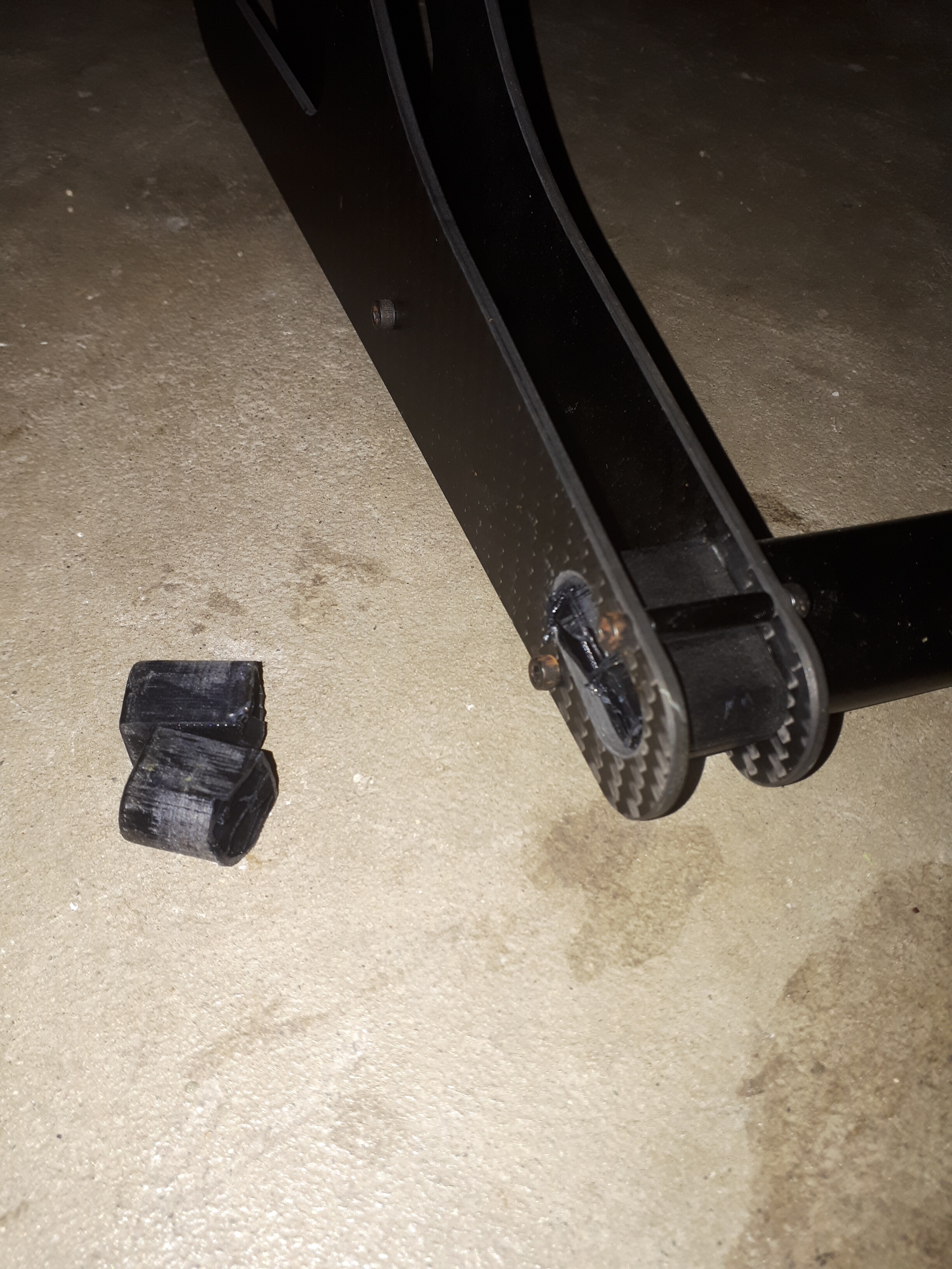
First landing damage.  . Came in after a really cold 20 minutes of cruising. The chill must’ve affected my brain. I was thinking the approach seemed fast but didn’t therefore reach the obvious conclusion that the slight wind had switched around. Fast downwind and damp early evening grass caused a slip. Basically I butt landed and caught the left side of the cage on the turf. Something went crack. Turned out to be the left leg-tube connector sheared.
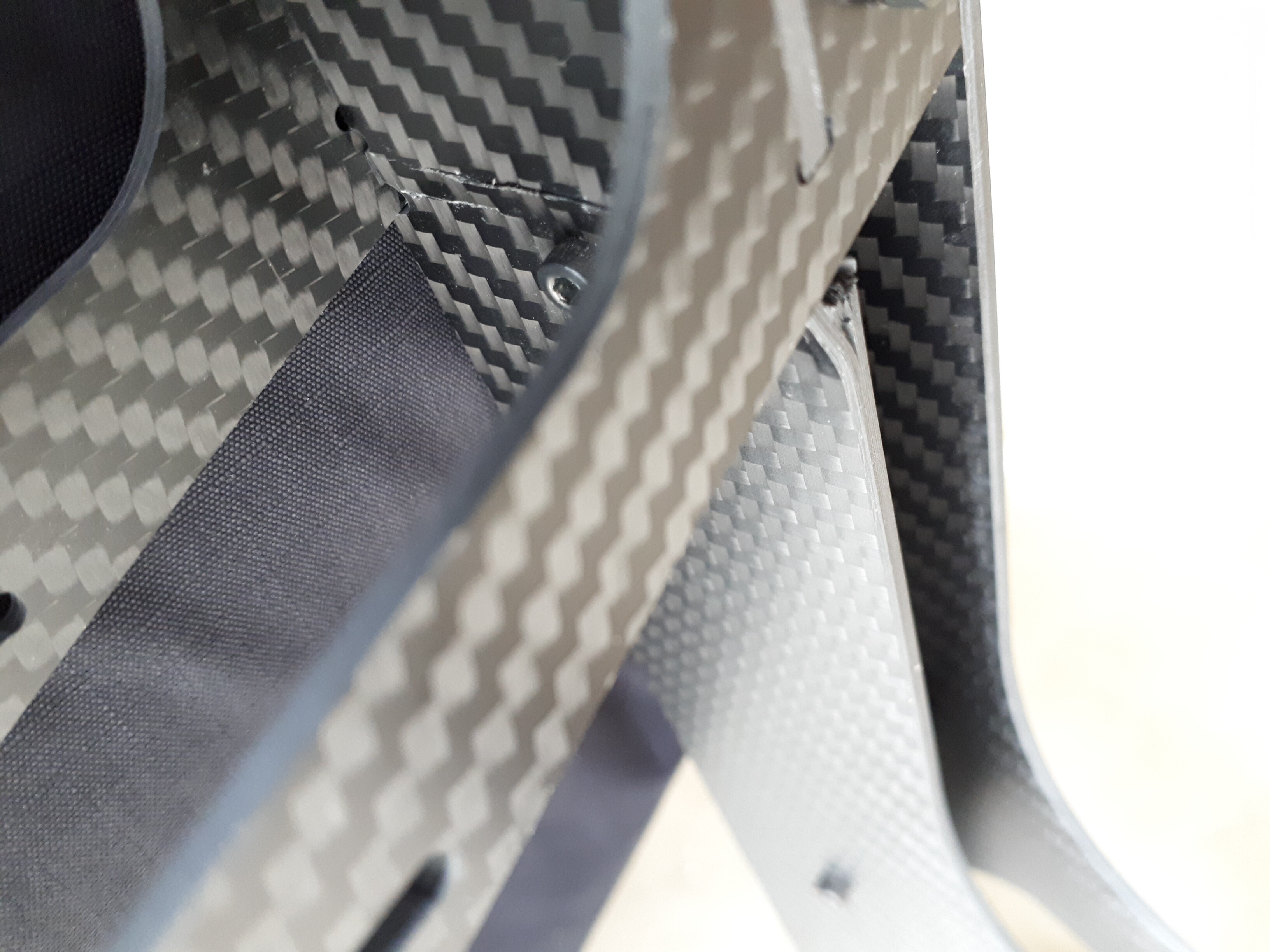
I also cracked both inner leg plates. They seem still solid enough and the outer plates are fine. The right one is the worst. These parts are not loaded in flight.
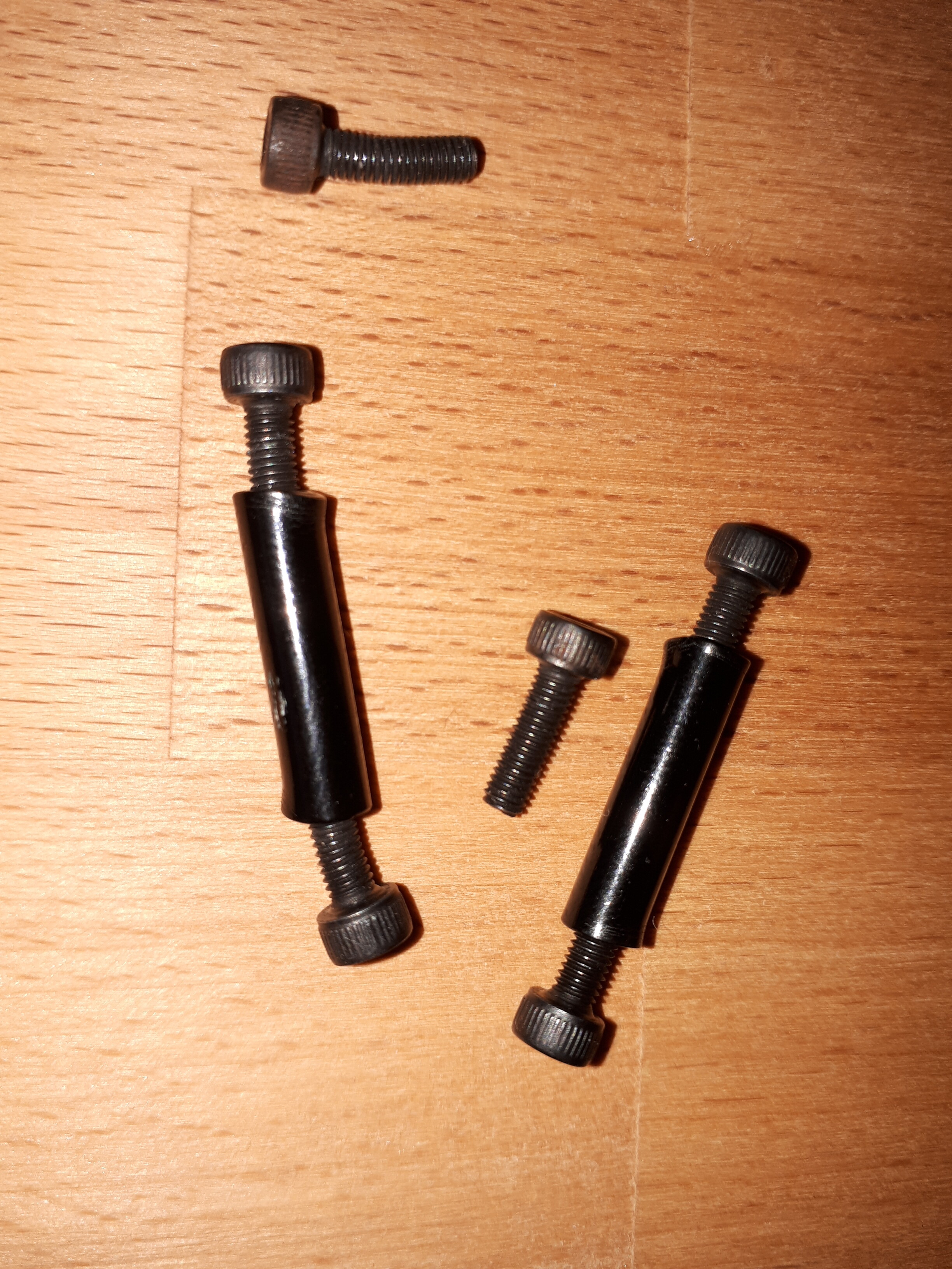
On the left leg a couple of the standoffs and a half dozen M3 screws bent.
One flight later I’ve discovered the right side leg-tube connected is also broken. I’ve epoxied it as well.
That is rough! Sorry buddy.
Chalking it up as a cheap lesson really. I’ve approached downwind before and had the presence of mind to switch directions. Just have to learn to stay focused on flying!
I’ve replaced the bent hardware from leftover parts I had.
Paul has sent me a replacement joiner for the price of shipping. While I’m waiting for that I’ve filled the broken joiner with epoxy (Gorilla brand) and stuck it back together. The breaks were very clean and there is plenty of mechanical surface inside for the epoxy to hold onto. That part weighs 30grams instead of 10 so I’ll probably swap in the new part when it arrives.
The cracked leg plates I’m going to just keep an eye on for now. The legs are still holding up the motor just fine.
Netting break
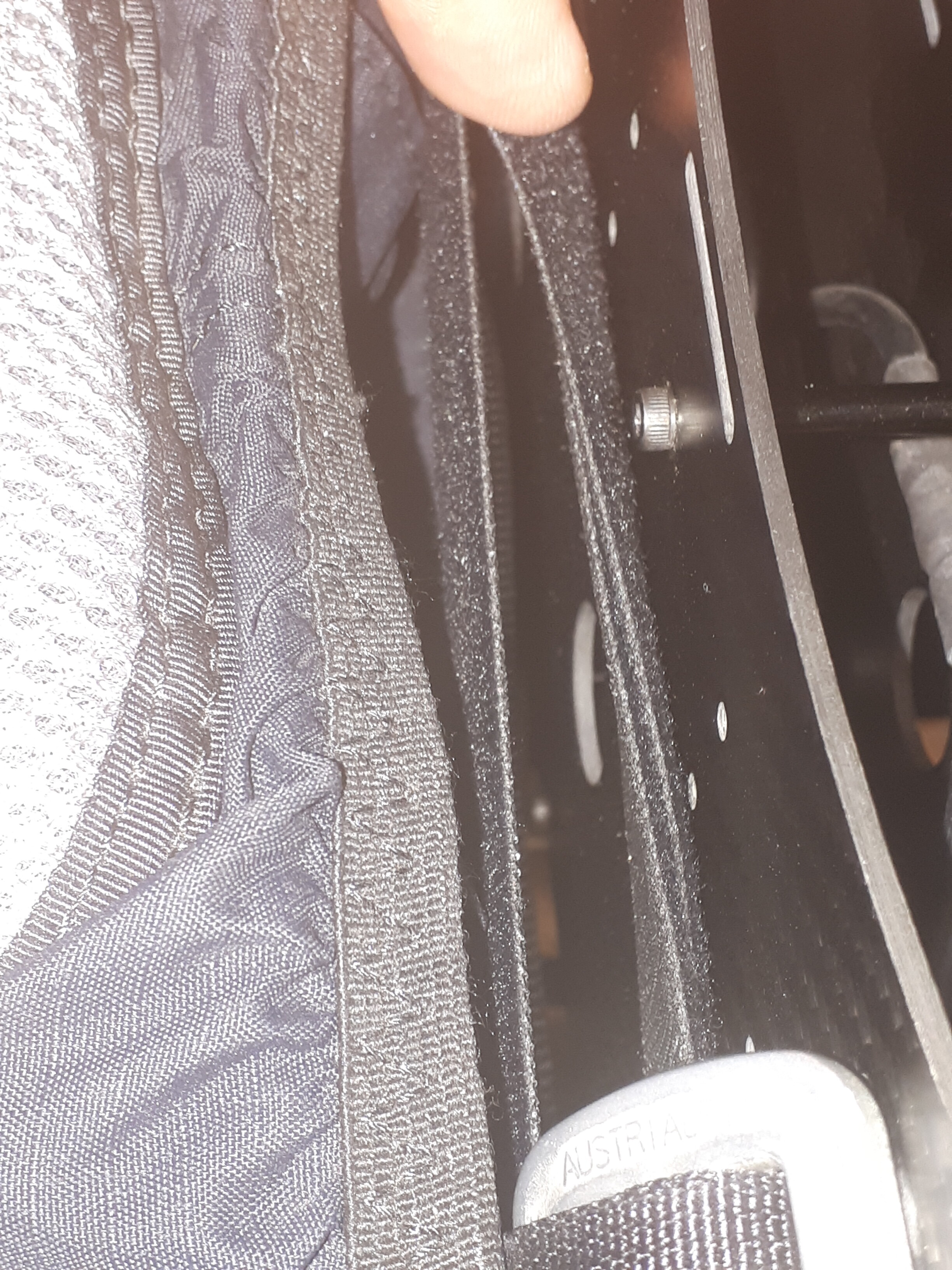
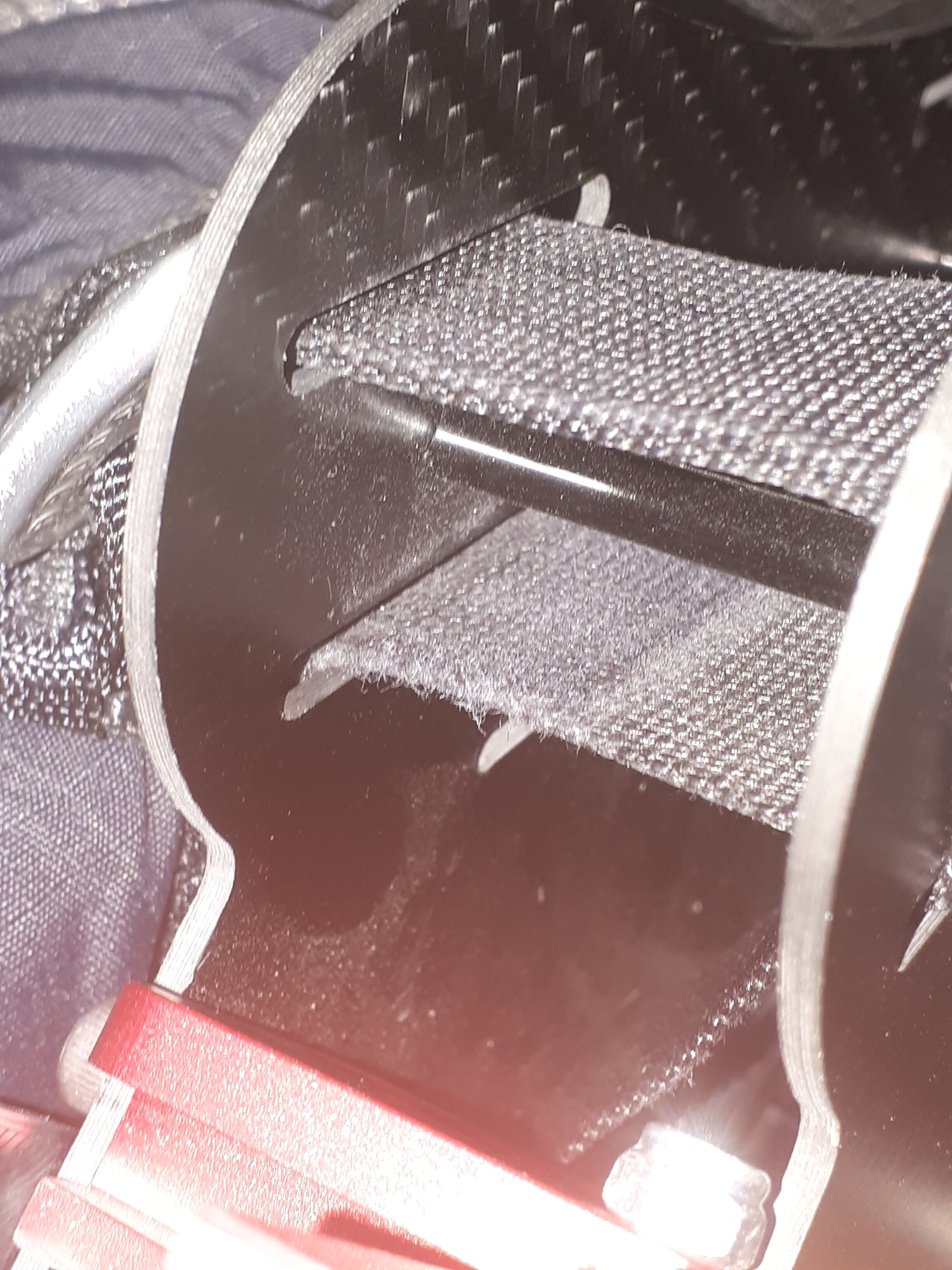
Noticed some wear on the upper harness straps just where they go through the lower slot in the frame. The right one only a little. The left one a bit more.
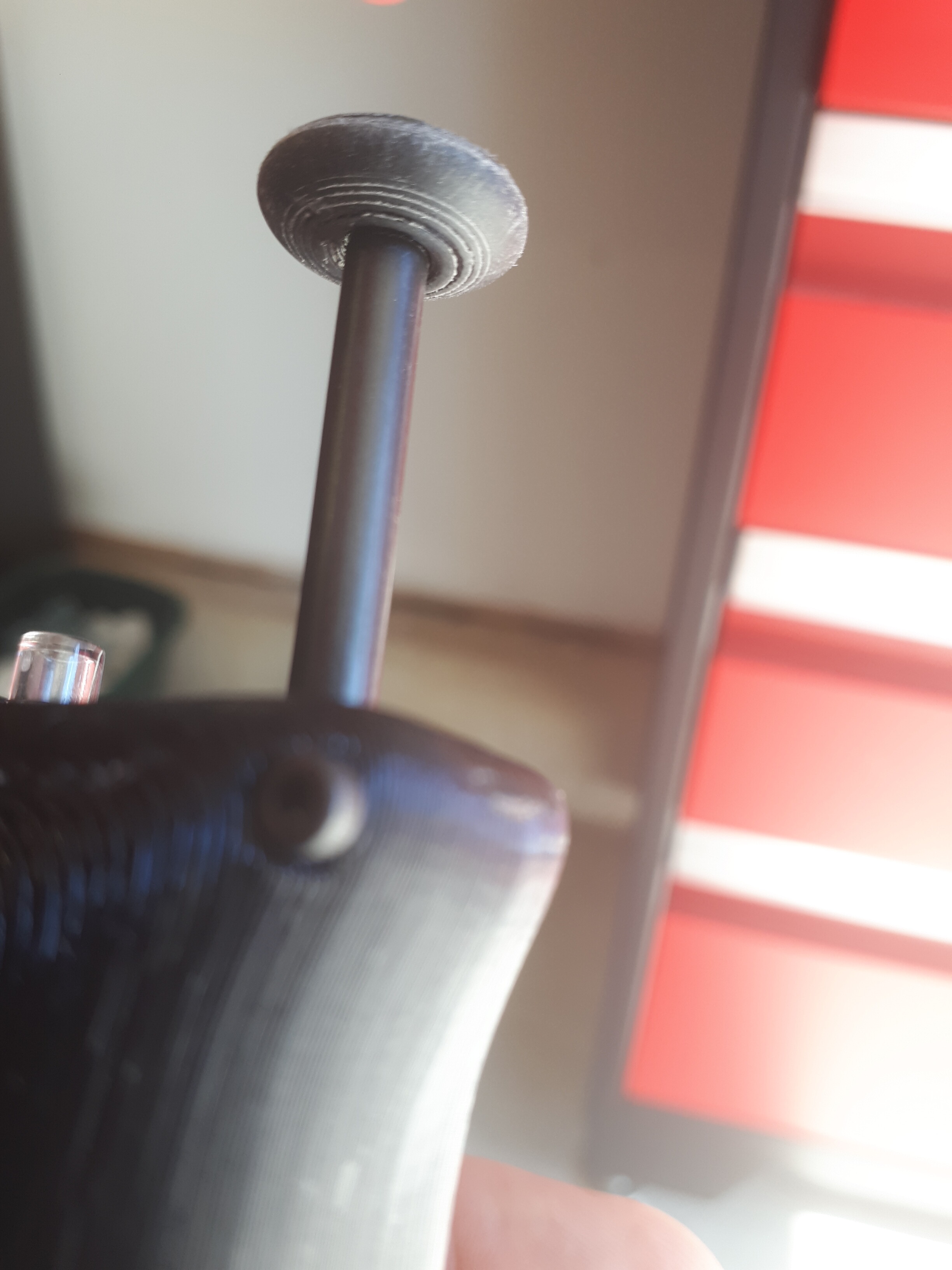
The plunger on the controller comes with a 3D printed thumb pad. I was concerned it could get caught by a line on launch so I’d simply unscrewed it. For 10 min flights this is not a problem. On 25 min flights my thumb was uncomfortable and dented.
I dug the pad out of the parts box, sanded it smooth, and reinstalled it flat side up.
Hiya just my 2 cents worth ,but would an 3d printed nverted which could fit ovet the top of the lever also help with comfort and minimum line snagging : potential -)
Yes. That’s exactly what that is. The 3D printed thumb pad I’m showing comes with the X4 kit already screwed to the plunger but flat side down.
Yes I would welcome a redesign of this part so it was even more tapered towards the handle. At full depression there is still about 5-8 mm gap between the bottom of the pad and the top of the handle. That space could be used to create a pad with a conical “V” shape. It could even be designed to fit over the plunger snug enough to not fall off, without being screwed to the plunger. That way if it did get a line wrapped right around it, it would just pull off and get lost. You would not loose the plunger which is part of an expensive electronic component soldered to the controller board inside the handle. I’m not a CAD guy. Anyone?
HI i dont have an openppg unit yet but may be able to help cad wise if you can post the dimeinsions of the Plunger then i can look at designing a clip on Part that may help … i use inventor at work and Fusion 360 for home use so between the 2 im sure we can come up with a retrofittable solution
Any idea where I can buy a replacement controller card?
Just email Zach or Paul or even DM them from these forums. If the past is on hand they’ll send you one and you can email them money or ?
Repair notes:
Tied up the netting breaks (found another one near the bottom corner) with some nylon thread. Also the epoxied leg-hoop joiner parts fell apart while handling the unit on the ground. Epoxy did not stick to the part at all and just completely let go after a few flights. Don’t think it would have possibly come apart under flight loads but hate to think what would happen if it did. Have now replaced the joiners with new ones received - thank you Paul.
Do you have a wiring diagram for the esc connections to the control board just bought an upgrade kit but no instructions provided
Thanks in advance
Dave uk
I used this for my batch 6: